Continue to Site

Welcome to our site!

Electro Tech is an online community (with over 170,000 members) who enjoy talking about and building electronic circuits, projects and gadgets. To participate you need to register. Registration is free. Click here to register now.

  • Welcome to our site! Electro Tech is an online community (with over 170,000 members) who enjoy talking about and building electronic circuits, projects and gadgets. To participate you need to register. Registration is free. Click here to register now.

Pulse Width Reader

Status
Not open for further replies.

Mr CCE

New Member
hi everyone,

I'm trying to calculate the width of a pulse that is an input to-let's say- RB0 pin of the PIC16F877A (portB configured as input).

I used the following algorithm:

trisb = 1
trisc = 0

dim counter as byte

a1:
IF RB0 = 0 then
goto a1
endif

while RB0 = 1
counter = counter +1
Wend

end

But the problem is that everytime I start the program, a different value of 'counter' is obtained.What gives??

thx in advance

the input is actually a square wave F = 2 Khz
 
Hi,
But the problem is that everytime I start the program, a different value of 'counter' is obtained.What gives??
I don't see where you initialized your counter variable. (ie: counter = 0)

You should take a look at using the capture compare module, as this will provide exactly what you are after. Check on Microchip's website for app notes.... and on the forums for CCP.
 
You need to wait for an edge. Think what will happen if the input is half way through a pulse.

Something like,
Code:
    while RB0 = 1 
    Wend

    while RB0 = 0 
    Wend

    while RB0 = 1 
        counter = counter +1
    Wend
Mike.
 
hey everyone,

I want to thank "BeeBop" and "Pommie" for their replies, now let's get straight to work.

about initializing the counter variable I already did it in the original program and I apologize for the misunderstanding but I only included the general algorithm just to show U guys how I'm thinking, but thanks anyway. Also, about the capture/compare module I'll start working on it right away so thanks for the advice.

The second point is wether the input is half way through a pulse, Pommie absolutely has a point so thanks man and I'll try your code.

I wanted to ask:
Is it possible that the microcontroller isn't fast enough? and if so, can I try getting a faster crystal? 'cause I'm using PIC16F877A with a 4 MHz crystal so how about a 20 MHz one?

thanks in advance!
 
Hi MrCCE,

hey everyone,

I wanted to ask:
Is it possible that the microcontroller isn't fast enough? and if so, can I try getting a faster crystal? 'cause I'm using PIC16F877A with a 4 MHz crystal so how about a 20 MHz one?

thanks in advance!

the input is actually a square wave F = 2 Khz

To satisfy Nyquist you need to sample at twice the frequency you are interrested in. 2 KHz is not that fast.... so I don't think it is the speed of the micro..

If you choose to go with the CCP module, you can select rising or falling edge. I'll try to find Microchips tips on using CCP.... and update this message when I do....

This isn't the one I was looking for, but will help:
https://www.electro-tech-online.com/custompdfs/2009/11/ccpwm.pdf

The one I want to direct you to is: CCP and ECCP Tips n Tricks app note
 
Last edited:
It's not a matter of Nyquist rate. The limited resolution is the problem!
The loop, in C code, will take an unspecified number of instruction cycles. Say it takes 10. Well, if the pulse is high anywhere from 20-29 cycles, that's a 2. And for that matter the looping time is unpredictable, C doesn't guarantee anything in this department. You might compile on a new compiler or even with different options and get a different value for a pulse lasting 27 instruction cycles. There is room for weirdness- if you use a 16-bit "integer" counter, the cycle which rolls over the lower byte counter might take more cycles as it carries. There's NO guarantee of number of instruction cycles in C. ASM code can guarantee it.

Find the loop in the ASM code in MPLAB, count the number of instructions, and count any instruction which modifies the program counter as requiring TWO cycles. A 4MHz xtal is a 1MHz instruction clock, so if your loop did require 10 instruction cycles, that's a total resolution of 50 codes for a 2KHz signal.

Be aware the time for the first loop is different due to the wait-to-go-high, then start-looping.

Interrupts (if used) must be disabled while counting, otherwise a loop which is interrupted will take a wildly different amount of time while the ISR executes.

The Input Capture was made for this. Otherwise, this seemingly simple task really has no elegant solution. I've had an accelerometer that looked great at first because it has these PWM "digital, for easy interfacing with a microcontroller" outputs, then saw there was no good way to interface it with a PIC. The PIC doesn't have 3x Capture inputs, and even the Capture can have a limited resolution creating numeric integrity problems. Basically looking at the options and doing the math, it came up as "wow- this can't be done with a PIC, not even close!"

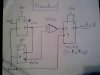
What device is this which gives its output in PWM format?
 
Last edited:
It's very easy to do Oznog. Like this;

Code:
  // read a pulse HI width using PIC TMR1

  TMR1L = 0;    
  TMR1H = 0;    
  while(!PORTB.F0);            // wait for RB0 to go LOW

  while(PORTB.F0);             // wait for RB0 to go HI
  T1CON = 0b00000001;          // start TMR1 on the RB0 / edge

  while(!PORTB.F0);            // wait for RB0 to go LOW
  T1CON = 0b00000000;          // stop TMR1 on the RB0 \ edge
  
  // now TMR1 contains the pulse width 16bit value,
  // max error is -2 or +2 TMR1 ticks.

Each while loop compiles to a BTFSS and GOTO so they take 3 TMR1 ticks to execute, so each loop introduces a random latency of 0, 1 or 2 ticks. But of course if sampled a number of times and averaged the error will pretty much cancel.

And if you sample over a lot of pulses you can get a very fine pulse width reading.
 
Last edited:
Done but......!

Hi everyone,

I want to thank "Pommie" for the code about pulse width reading which has proven to be more successful than my if loops; what happened is that I created another program for one of the Microcontrollers to act as an oscillator -variable frequency- and I got a specific pulse width for each frequency, what I want to say is that it was a complete success; when the output of the ocsillator is directly connected to the reading pin of the
PIC16F877A, that is.

On the other hand, when I started using my wireless kit, the values obtained for pulse width's were not so specific; for example let's say a pulse gave me a reading of 42 when using wires, turned out to be a number in the neighbourhood of 42: 36/38/42/43/45 when I used the RF tranmitter and receiver, knowing that my RF modules are tested to be 100% efficient in transmitting periodic square waves as well as bytes of different values(amplitude regulated and filtered).

Again, What gives??

thx in advance
 
What are the RF modules that you're using?
 
The problem with RF modules is noise. Fortunately noise tends to be in short bursts and so you can just check the length of the pulse received and reject any that are far too short.

Mike.
 
Also if you believe.
100% efficient in transmitting periodic square waves
can be true you don't understand RF transmition.
 
About RF.....

oh!.... LOL sorry about the 100% efficiency bit I admit it it's a bit non-professional so go easy on me...(LOL).

Of course "Sceadwian" you know what I mean I was going for "a very good reception with a minimal amount of error" and that's all friend.I transmit bytes of different values with it and they're all perfectly received and viewed on the oscilloscope.

About your first question "What are the RF modules?": the receiver is YS
CWC6 and the transmitter is YS FST8:rolleyes:
 
I found page that refered to the reciever but was unable to find a datasheet for it, do you have one? These modules usually require encoding of the transmitted signal, and if you need a low error rate you'll have to send the signal digtallly with error detection/correction.
 
About the modules....

Hi everyone,

Sorry about being late with the response, I've been very, very busy lately.
About the RF modules, actually all I have are the information from "Alibaba.com"
and I requested a friend to ship them for me all the way from China, so it's like that.

About the encoding bit, it's true that I might get more accurate results if the the data were encoded.I'll try it out.

Cheers;)
 
New results.........

Hi everyone,

These modules usually require encoding of the transmitted signal, and if you need a low error rate you'll have to send the signal digitally with error detection/correction.

Right now I tried to encode the data using a 1-bit differential ecoder and then I directly applied it to the corresponding decoder.I could say the process was a success, but I obtained exactly DOUBLE the original value of the pulse width, that is, the result was 84 but without the 1-bit differential codec it was 42!!!

Now I could simply divide by two in the microcontroller program, but, what's the cause of this?

I'll attach schematics of the 1-bit differential codec that I used down below

thx in advance.
 

Attachments

  • 1-bit differential decoder.jpg
    1-bit differential decoder.jpg
    59.4 KB · Views: 186
  • 1-bit differential encoder.jpg
    1-bit differential encoder.jpg
    34.5 KB · Views: 174
The next step....

Hi everyone,

Last time I tried to encode the data before transmitting it and the result was successful, I was able to distinguish between 3 different signals by reading the width of their pulse: 1KHz, 1.5 KHz, and 3 KHz.

Now the next thing that I'm working on is establishing communication between two microcontrollers where one of them will create a variable the value of which will indicate the time that the signal travelled.

I'm gonna try this out (I've never done this before) but I want your opinion:
- Is it possible and Has it been done before on a small scale?

thx in advance
 
Status
Not open for further replies.

Latest threads

New Articles From Microcontroller Tips

Back
Top