Continue to Site

Welcome to our site!

Electro Tech is an online community (with over 170,000 members) who enjoy talking about and building electronic circuits, projects and gadgets. To participate you need to register. Registration is free. Click here to register now.

  • Welcome to our site! Electro Tech is an online community (with over 170,000 members) who enjoy talking about and building electronic circuits, projects and gadgets. To participate you need to register. Registration is free. Click here to register now.

Pulse Modulate Microwave Oven

Status
Not open for further replies.

pnielsen

Member
What is the most straightforward design option for modulating the output of a microwave oven with a 30Hz square wave? I am referring to an electronic modifiication, not rotating baffles, etc.

If complete on/off switching is not practical, a reduction of about 50% would be acceptable.

This is intended to be part of a working, fully assembled oven.
 

Attachments

  • microwave_oven_circuit.jpg
    microwave_oven_circuit.jpg
    24.7 KB · Views: 207
first, i'll tell you that messing with the secondary side of a microwave oven circuit is VERY DANGEROUS. the charge on the capacitor can kill instantaneously. never assume the bleeder resistor inside the capacitor works. if you make a mistake, you will never know about it. i can't stress this enough. the high voltage in a microwave oven is in a class by itself. the capacitor is capable of several amperes of discharge current. if you work on a microwave, follow the manufacturer's procedure for discharging the secondary, even if you are only working on the primary circuit.

second, the transformer is designed specifically for whichever line frequency is in use in it's destination country. some countries use 50Hz, some use 60Hz. you cannot drive the transformer with 30Hz. the way most microwave ovens achieve variable cooking power is by turning the primary on and off over successive 10sec intervals. so, 50% power would be on 5sec, off 5sec. 80% power would be on 8sec, off 2sec. this works because the thermal effects average out in the food being cooked. this is the preferred method of regulating the power in a microwave oven, and it works well. using a method of reducing the secondary voltage doesn't work well because the magnetron voltage has to be above a particular threshold for the magnetron to work right. you could however, change the duty cycle interval, to one second, so you would have on for 1/2sec-off 1/2sec for 50% power. but the reason they do the 10sec interval is to reduce wear and tear on the primary circuit relay.
 
Thanks for the warning, which I am already aware of. I was expecting to effect the modulation at the primary side.

From your description, it seems the relay (which I assume is mechanical) could be activated at any low frequency. If so, looking at the diagram below (as an example), I would simply need to insert a square wave at Q7C3. No need to touch or expose the HV components.

I would probably drop the modulation frequency to 10Hz so it is further away from 50/60Hz. The intended effect is to cycle the magnetron output on and off at that frequency. This is for an experimental application, so I am not too concerned if the life of the relay is reduced accordingly.

Comments and/or further warnings welcome.
 

Attachments

  • microwave_control_circuit.jpg
    microwave_control_circuit.jpg
    95 KB · Views: 174
I doubt the magnetron heater element would like being pulsed rapidly. The pulsing would be additional to its normal mains frequency sinusoidal energisation, so could add to thermal stresses.
 
Referring back to the reply by unclejed, in typical use the power is already cycled at a far slower rate to vary "cooking power". By that standard, continuous 10Hz would seem to be an improvement over 5 sec. off 5 sec. on, etc.
 
Referring back to the reply by unclejed, in typical use the power is already cycled at a far slower rate to vary "cooking power". By that standard, continuous 10Hz would seem to be an improvement over 5 sec. off 5 sec. on, etc.

It might be, IF you weren't pulsing the heater as well - that's why they use the 10 second pulse cycle, so the heater has time to warm up and the magnetron has time to start oscillating.
 
It appears you are saying that the heater would cool too much if pulsed at 10Hz.

If so, this might be addressed by increasing the duty cycle of the 10Hz squarewave, maybe to something like 80%, so in effect the magnetron never stops oscillating.
 
It appears you are saying that the heater would cool too much if pulsed at 10Hz.

If so, this might be addressed by increasing the duty cycle of the 10Hz squarewave, maybe to something like 80%, so in effect the magnetron never stops oscillating.

It's PWM, if you pulse it at 50% then you get 50% power, and thus only 50% of the heat in the heater.

If you increase the duty cycle to 80%, then it 'probably' will run OK, but is 80% power all you're after?.

As always in these threads, what are actually trying to do?, and why?.
 
I understand there must be compromises whenever you try to make something do what it was not designed for. But if I know it is feasible, I can then test the concept on the bench.
 
It appears you are saying that the heater would cool too much if pulsed at 10Hz.

Not exactly. It will never get warm enough for the magnetron ot fire up and do its thing. Magentrons are basically high powered vacuum tubes and thusly have a minimal temperature they will work at which means that if the tube heater is too cold they just don't work at all.

What do you think you will gain from using a faster cycle rate? Foodstuffs are heated by the microwave frequency vibration of their water molecules and that water plus everything else that makes up the food item has a thermal mass that only reacts to thermal changes so fast or slow due to its rates of thermal conductance given a fixed energy input to which when the energy is spread out over large area or volume and mass the overall rate of temperature change point to point is fairly slow.

Given that a duty cycle under the typical 10 - 20 second is rather pointless and will not give any substantial gains ins system efficiency or cooking speeds but will drastically affect the service life of the hardware of the oven.

The thing is, microwave oven tech is not in it infancy at this point. They've been around and in mass use for 40+ years and were well understood cooking tech some time before that!
 
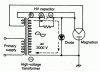
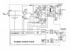
the circuit you uploaded is from a microwave oven that uses a flyback converter operating at a higher frequency than the AC power. you have to realize that the power transformer in the first schematic is for 50Hz, the second one somewhere around 5-10kHz. if you try driving the first one at 10hz, you will lose most of your energy as heat in the transformer which is designed for 50Hz operation. the reactance of the primary winding will be much lower, but the wire resistance will stay the same, this also means that the reactance will no longer have the same phase difference from the wire resistance, and you will overheat the primary. i'm beginning to get the picture this project isn't about cooking, or the 10 second duty cycle window wouldn't be an issue. i'm guessing you want to make either a radar (it's going to take a lot more than simple modifications to make that work) or something a bit more hazardous???

like i said earlier, magnetrons are not linear. they act like a regular diode below a certain voltage when the threshold voltage is reached, electrons are no longer traveling directly to the plate. the magnetic field curves their path, and they begin spiralling towards the plate. at a certain critical voltage the electrons are just grazing across the surface of the plate, and this sets up oscillation in the resonant cavities in the plate, which is the source of the microwave RF. above this critical voltage, the electrons never get near the plate, and the oscillation stops. now there's no tube current, no microwaves being produced, this is the cutoff voltage of the magnetron. the active portion of the curve where microwaves are being generated is actually a negative resistance region. if you pulse width modulate the power going into the transformer, the voltage on the secondary side will average out, and you may end up with the tube in diode mode, the tube in active mode (a very narrow region) or in cutoff mode. you want to avoid diode mode, because the cathode will likely overheat and burn out, and you want to avoid cutoff mode, because the voltage across an open circuit tube will likely find somewhere to arc over. within the active portion of the curve, there is really very little variation in power output, except for the nonlinear edges between diode mode and active mode, and between cutoff mode and active mode. the active mode is so narrowly defined that fine grained control of output power is not really possible. if you want a source of microwaves that can be easily controlled, it's better to use a reflex klystron, or a Gunn diode. when i was in high school i found a box of some really weird looking parts in the electronics shop. the teacher said i could take them home, as they were just taking up space. when i got the box home i got a better chance to see what was there. there were a bunch of reflex klystrons similar to this one https://www.bmisurplus.com/products/46200-etheric-beam-locator-varian-va-220b-klystron-tube . there were two demo units that had an amplitude modulated klystron in one side, and a waveguide with crystal detector on the other side, and with horn antennas mounted on the boxes, you could talk full duplex on them, but their range was limited to about 10 feet.
 
50% power would be on 5sec, off 5sec. 80% power would be on 8sec, off 2sec. this works because the thermal effects average out in the food being cooked

This is NOT TRUE for a microwave oven.

Real numbers:
27s on 100%
21s on 6s off ~ 70%
15s on 12s off ~50%
9s on 13s off ~30%
5s on 22s off ~10%

The magnetron is only powered on the negative half cycle.
The filament needs time to heat up.
 
UncleJed... that's probably the most informative thing I've ever read about magnetrons. Of no practical use to me, at least, but still fascinating!
 
You can check the power levels using the IEC705 method. http://www.celtek-electronics.com/microwave-leakage/microwave-oven-power-test

You won;t exactly know how many seconds it takes the filament to warm up, but 2-3 sec seems to be about right. So, you could fine tune the powers for your specific oven, They claim within like 15%, so interpolate knowing the powers using the numbers above. During your test, you can have your controller do the stop start more precisely.
 
This is NOT TRUE for a microwave oven.

Real numbers:
27s on 100%
21s on 6s off ~ 70%
15s on 12s off ~50%
9s on 13s off ~30%
5s on 22s off ~10%

The magnetron is only powered on the negative half cycle.
The filament needs time to heat up.

different manufacturers use different integration times, but the ratios are similar. i apologize if my simplification of the duty cycle caused any confusion.

you can get a fairly accurate figure for output power, by placing a container in the microwave with 1 liter of water in it, and cook for 60 seconds. each degC rise in temp=70W
 
Last edited:
The numbers I posted came out of a training manual. Normally you think that a 50% duty cycle might be 50% power, but who knows about voltage or V^2 being proportional to power and the 2-3 seconds where nothing happens, so 10 Hz (10 times a second) isn't going to work. The lifetime of the magnetron will also be a risk.

Probably if you say 60 seconds 10%, you just get 6s of heating with 3s of warm up, so, the microwave stays on for 60s (just noise) happens just to keep the consumer happy.
 
I understand the heater takes a certain amount of time to heat up. But my point was that by using a continuous 10Hz switching signal to the relay with a duty cycle of about 80% the heater would virtually be on all the time. IOW you have the advantage of sufficient heating plus the desired 10Hz pulse.

As per my earlier post, I would switch the ACpowering the transformer primary using the oven's inbuilt cycling relay, not drive the transformer directly. So its frequency response does not appear to be relevant. I am not concerned about a distorted wave form so long as there is 10Hz component present.

The purpose of this setup relates to a chemical process, not cooking food.
 
Would it be an option to energise the heater continuously, and just switch the HT (by switching the HT transformer primary)?
 
I would switch the ACpowering the transformer primary using the oven's inbuilt cycling relay
Maybe ok for a short time, but the relay won't last long if its rated life is, say, 10^5 operations.
 
Would it be an option to energise the heater continuously, and just switch the HT (by switching the HT transformer primary)?
you would need a separate filament transformer with 5-10kV isolation (more like 10kV because the magnetron itself is part of a voltage doubler circuit), maybe from an old radar set or maybe an old >1kW transmitter. a magnetron filament needs 3V at a couple of amps to operate. the filament would definitely last longer if it remained on, even at a reduced voltage, either continuously or during a cooking session where the power to the mag is being switched on and off. this is true of most vacuum tubes, and is why tube type TVs ran the filaments at a lower idle voltage while the TV was switched off (simple circuit, the switch for the filament string went through a diode when the TV was off, and bypassed the diode when the TV was on)
 
Status
Not open for further replies.

Latest threads

New Articles From Microcontroller Tips

Back
Top