Continue to Site

Welcome to our site!

Electro Tech is an online community (with over 170,000 members) who enjoy talking about and building electronic circuits, projects and gadgets. To participate you need to register. Registration is free. Click here to register now.

  • Welcome to our site! Electro Tech is an online community (with over 170,000 members) who enjoy talking about and building electronic circuits, projects and gadgets. To participate you need to register. Registration is free. Click here to register now.

Pulse Modulate Microwave Oven

Status
Not open for further replies.
Maybe ok for a short time, but the relay won't last long if its rated life is, say, 10^5 operations.
an option here would be to replace the relay with a 20A SSR, then there would be no moving parts.
 
I understand the heater takes a certain amount of time to heat up. But my point was that by using a continuous 10Hz switching signal to the relay with a duty cycle of about 80% the heater would virtually be on all the time. IOW you have the advantage of sufficient heating plus the desired 10Hz pulse.

As per my earlier post, I would switch the ACpowering the transformer primary using the oven's inbuilt cycling relay, not drive the transformer directly. So its frequency response does not appear to be relevant. I am not concerned about a distorted wave form so long as there is 10Hz component present.

The purpose of this setup relates to a chemical process, not cooking food.
if you need something this specific, it would be better to make a special power supply for the magnetron, rather than modifying the existing one (which is designed for a particular purpose and operating cycle). what you really seem to want here is a -5kV/200mA power supply that can be switched electronically. you're actually looking more for a circuit that resembles a radar transmitter than an oven. i don't think you will find any solid state devices up to the task, unless you use a transistor cascade. you would be switching a kilowatt, a daunting enough task at hundreds of volts, even more so at 5kV. maybe you don't need high PRRs like a radar, but the switching would be similar in construction. you can't do it with the circuit in the oven, because the cap is directly connected to the filament winding, and the mag is actually the second diode of a voltage doubler. you would need a continuous AC supply to the filament, and a -5kv power supply, and a switching device (electronic, not electromechanical) between the power supply and the filament winding. because of the voltages and currents involved, this will not be cheap or easy.

you will also want to enclose the whole thing in a box that has service interlocks. this isn't a weekend project. it has to be well thought out, and as much as possible idiot proof.

you saw my warning in post#2, please keep it in mind.
 
Last edited:
you would need a separate filament transformer with 5-10kV isolation (more like 10kV because the magnetron itself is part of a voltage doubler circuit), maybe from an old radar set or maybe an old >1kW transmitter. a magnetron filament needs 3V at a couple of amps to operate.

You're missing the blindingly obvious - use a second microwave oven transformer to provide the heater voltage, ignoring the HV winding.

It should be dead easy to get a scrap oven for free.
 
true, from the OPs insistence that it has to be pulsed at 10hz, what he's looking for is beyond the capabilities of a normal microwave oven power supply. he's looking at something more closely resembling a radar transmitter. a 10hz PRR would be good for.... about a 9300 mile range window if it were used for radar. i don't think a 1kW radar would work at that range. it doesn't follow curvature of the earth, and theres a lot of water vapor in the atmosphere, so 2.4Ghz has a lot of atmospheric losses.
 
Last edited:
Maybe you need to modify an inverter based microwave?

That's the power supply I would be looking at given trying to cycle a common iron core 50 - 60 Hz rated transformer at 10 HZ is just asking for trouble due to constant high inrush current cycling given that it takes several cycles for a iron core transformer that being operated at near saturation mode to get is magnetic fields going.

I don't recall what exactly is the effect that in play but for whatever reason when a iron core transformer is cycled on it takes up to several cycles to get it magnetic field oscillating to which doing a 10 HZ ,with dead time delay, between powered on cycles operation would mean the transformer would be forever in peak inrush start up mode only getting 2 - 4 cycles per run plus trying to carry whatever loads the magnetron takes while it's doing it.

Then on top of that the voltage multiplier circuit needs a few cycles to get itself charged up and the magnetron driving power up to speed as well. Average power and current values would look good but the reality is the peaks of each during the true running times would be horrific. Near dead short operation equivalents.
 
the inverter based one could be used as a power supply, but the filament still needs to be run at 100% duty cycle, so that might be provided by a transformer. i'm not sure what the ramp up/down times are like for the inverter based ovens, but at least that could be controlled electronically. only work i've done on the inverter based ones are replacing the inverter PCB and replacing the mag. the only inverter ones i've seen in the shop were Panasonic. the ramp times for the inverter are likely very short, as the FBT is switched at something close to 100kHz.
 
that's strange, both links get converted to the first link... the second one being use of the inverter to power a linear amplifier. i had to type the visible text into the browser to go there.
 
@unclejed613 Agree. I fixed it by putting URL tags on the second link.

I've been known to find all sorts of bugs. A graduate student did his thesis on a networked terminal Handler back in the late 70's and he say see if you can break it. I walked over to a logged out terminal and typed 3 characters. Crash. I guessed that he didn't take into account a specific sequence of characters that made the character position -1, I think.

I recently found a bug with their Staples self-service copiers. Scan in portrait - prints in landscape under certain conditions. The one I use all the time, but apparently no one else does.
 
Last edited:
i have friends that really should consider a career in software testing. :facepalm:
 
Given the noted problems associated with a 50/60Hz transformer for this application, the consensus seems to be that an inverter based microwave oven power supply is required.

Referring again to the circuit below, what I propose to do is switch the LED side of an optocoupler with a 10Hz 80% duty cycle square wave and connect the other side in series with the base drive of Q702.

Does anyone see a problem with this, or have a better method?
 

Attachments

  • inverter_microwave_supply.png
    inverter_microwave_supply.png
    192.3 KB · Views: 151
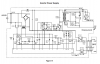
you need to supply your filament continuously. if you don't, you will not have the proper electron emission for the magnetron to oscillate, and you will shorten the life of the tube. it looks like the opto for controlling the inverter is IC701. you might want to find out what IC702 is used for, it provides feedback to the controller, but it's purpose is not clear. it could be a protection circuit, with the inverter operation monitored by pins 10, 11, and 12, and pins 7, and 8 provide overcurrent monitoring. if you try controlling the inverter by modifying the drive line for Q702, you might trip one of the protection circuits. it's better to use IC701. keep in mind that the whole primary side of this inverter is floating at about 60Vac, which means that everything connected to it externally must be done through opto isolators, and you can't clip a scope ground to the - side of the bridge rectifier. if you need to look at stuff on the primary side, the safest way is to use a dual channel scope, with ground connected to the chassis ground, channel 2 probe connected to the -rail of the bridge rectifier, and the scope in ADD mode, with channel 2 inverted. you connect both probes to the hot ground, and adjust gain on channel 2 to null out the sine wave. both channels should be set at 20v/cm or 10v/cm. you leave channel 2 probe on the hot ground and use ch1 for measurements. you don't need an isolation transformer if you use this differential mode scope setup, so you will never have the scope ground connected to a hot ground. using an isolation transformer solves one problem and creates another, it causes the chassis ground of the unit under test to float at 60V once a scope ground is connected to the hot side of the supply.
 
Last edited:
Further to your analysis above, I now understand the latency of the heating element would preclude the type of 10Hz "beam" switching I had originally proposed. The only viable solution appears to be a rotating metal baffle to interupt it at the desired rate.

Anyway, I have learned a lot about microwave ovens and what you cannot do with them.
 
The teardown sort of suggested that the unit has to run at 40% power to be able to continuously modulate it. When it's less than 40% it uses the long time on off proportionality method of the normal microwaves. So, maybe you need to warm the filament for 30 s, before trying to modulate. You can't directly modulate at 10 hz. Your turning off the power signal at 10 Hz.

I now understand the latency of the heating element would preclude the type of 10Hz "beam" switching I had originally proposed.

You MIGHT be able to do it. The filament would not necessarily cool down sufficiently, but the control circuit could put a stop to it. You just need a pre-heat mode
Not sure if you can make a shutter for diversion for 30 s. e.g. full power 30s ; shutter closed followed my modulating the power signal at a 10 Hz rate; Shutter open,
 
as it's been noted, using a separate transformer for the filament would work, and use the existing control opto to switch the inverter supply on and off. the only other application i've seen for a standard oven magnetron is to drive a sulfur plasma lamp.
 
Status
Not open for further replies.

Latest threads

New Articles From Microcontroller Tips

Back
Top