Electro Tech is an online community (with over 170,000 members) who enjoy talking about and building electronic circuits, projects and gadgets. To participate you need to register. Registration is free. Click here to register now.
Welcome to our site! Electro Tech is an online community (with over 170,000 members) who enjoy talking about and building electronic circuits, projects and gadgets. To participate you need to register. Registration is free. Click here to register now.
I need help to do a circuit that makes the follwing:
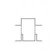
in the positive and in the negative transition i want to make a pulse and then stays off (see figure).
How i do that?
It seems simple but i can´t do that...
Your right...
I will use NANDS to do the XOR (see image) being my output B' my input B. My output B' it's after my RC network.
Thanks to all...
Merry Christmas.
I think that the initial ideia (with Ron H help) with XOR won't work, because when my signal goes down 0 and 0 with XOR is 0, and i want to do a 1 level
What Ron is saying is you should delay one of the XOR inputs. The time delay on the second input will have direct control over the pulse widths on the output, so in this example, you will need to the know the output delay times of the two inverters (tPHL and tPLH). Before anybody whines, there are other ways to generate a delay as well.
This threads getting quite long now, and producing a little controversy, but it's never been explained what it's required for? - with full information a solution may be much easier?.
This site uses cookies to help personalise content, tailor your experience and to keep you logged in if you register.
By continuing to use this site, you are consenting to our use of cookies.