Hello, I am new in the forum, so I want to say hello to all of you.
Well, Before Anything, My natal language is Spanish so please forgive me If I don´t write something right.
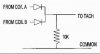
Well I Have installed an Aftermarket tachometer with shift light on my dodge neon 2003, but there is a problem, my tach function only for, 4,3, and pulses per revolution (ppm), but my ignition coil works at one ppm, My ignition coil sends to signals, one for cylinders 1,3, and other for 2,4 cylinders, so´I hooked up my tach to one of this signals and I am receiving only the half of the RPM´s readings, but, I want my tach to work normally, so one person, told me that I could conect each coil signal to a rectifier diode, so when I put them togheter i would receive the full RPM´s, but it didn,t worked, each coil signal worked fine whe it was alone, and I say that it worked fine because i received the usual hal of rpm´s, but when I putted the to lines together, Nothing happend, I don´t know why if each one alone worked well, so I think that a pulse doubler could work, and instead of wiring the to coil lines toguether with the diodes, I could keep using one, but with the pulse doubler I can get a double pulse signal so my tach reads the real RPM´s.
Does Anyone can help me to build a Pulse doubler, or can you help me to solve the problem with the diodes??
Thank you very much,
Well, Before Anything, My natal language is Spanish so please forgive me If I don´t write something right.
Well I Have installed an Aftermarket tachometer with shift light on my dodge neon 2003, but there is a problem, my tach function only for, 4,3, and pulses per revolution (ppm), but my ignition coil works at one ppm, My ignition coil sends to signals, one for cylinders 1,3, and other for 2,4 cylinders, so´I hooked up my tach to one of this signals and I am receiving only the half of the RPM´s readings, but, I want my tach to work normally, so one person, told me that I could conect each coil signal to a rectifier diode, so when I put them togheter i would receive the full RPM´s, but it didn,t worked, each coil signal worked fine whe it was alone, and I say that it worked fine because i received the usual hal of rpm´s, but when I putted the to lines together, Nothing happend, I don´t know why if each one alone worked well, so I think that a pulse doubler could work, and instead of wiring the to coil lines toguether with the diodes, I could keep using one, but with the pulse doubler I can get a double pulse signal so my tach reads the real RPM´s.
Does Anyone can help me to build a Pulse doubler, or can you help me to solve the problem with the diodes??
Thank you very much,