Continue to Site

Welcome to our site!

Electro Tech is an online community (with over 170,000 members) who enjoy talking about and building electronic circuits, projects and gadgets. To participate you need to register. Registration is free. Click here to register now.

  • Welcome to our site! Electro Tech is an online community (with over 170,000 members) who enjoy talking about and building electronic circuits, projects and gadgets. To participate you need to register. Registration is free. Click here to register now.

pull up / down resistor within ECU, please explain.

Status
Not open for further replies.

reflected

New Member
Hey guys,

can anyone please explain to me how to read and understand pull-up/down resistors inside the ecm schematics?

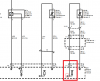
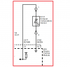
see the image...I marked the pull-up resistor and I would like to know how it works....

how does pull up/down works?
what is the triangle sign in the pull up stand for?

**broken link removed**

Thanks
 

Attachments

  • pull up_down r.png
    pull up_down r.png
    15.4 KB · Views: 1,025
Consider the pull-up first. The top end of the pull-up is tied to a regulated reference voltage, usually 5.00V The bottom end of the Engine Coolant sensor is tied to "engine ground". The junction (the sideways triangle you asked about) is the common point between the top of the Coolant Sensor and the bottom end of the pull-up.

In this schematic, the sideways triangle just means "this point goes somewhere else". In this case, it goes to a Analog to Digital converter channel in the Engine Control uProcessor.

The pull-up resistor value is chosen so that at normal engine temperature, its resistance is equal to the resistance of the Coolant sensor. The two series resistances form a voltage divider, so if they are equal, the voltage fed to the ECU would be about one-half of 5V, or 2.5V. Usually, the coolant sensor resistance decreases with increasing temperature (Neg tempco), so as the engine gets hotter, the voltage to the ECU decreases. It is trivial to reverse this in the ECU program...

The pull-down logic is the reverse of what I just described...
 
Here is an illustration of how the pull-up creates a ratiometric voltage divider. I created a model of a phony Coolant Sensor. The Red plot is its resistance vs temperature. I made up this curve, but you will find that a real Coolant sensor will have a similar Resistance vs Temperature curve.

I connect it to a 100Ω pull-up resistor fed from 5V, and also plot the voltage V(ecu) at the junction between the pull-up and the sensor vs the Temperature. Note how the voltage varies as the Temperature changes. This is the voltage that the ECU would be measuring using one of its A/D channels...

3.gif
 
The key here is "ratiometric". What this means is that the sensor voltages are not absolute. e.g. 0-5 V output. They are 0 to Vcc. Vcc is generally "supposed" to be 5V, but it could change.

Many times 1/2 Vcc is used as a reference. This is to get the signal within the common mode range of the A/D. So, 1/2 Vcc may be the sensor zero. With a 0 and 5 V nominal supply, it's very difficult to achieve 0 and Vcc.

The pull-up/pull-down may also provide a "unplugged sensor" value.

MOST of the time when we speak of a pull-up we refer to digital logic. CMOS, for instance does not like floating inputs.

In your case though, the pull-up is providing a radiometric reference. What the supply is, not some absolute number like 5V. SO, if the tolerances are +-10%. Vref could be 5.1 V. In reality, it's the the voltage at the same time the measurement is performed. V(t) could be 5.08 V for one measurements and 5.1 for another. The measured value, A % of Vref will be the same in both cases.
 
Hey guys,
First of all thanks a lot for the answers. I read and learn. really appreciate it!
I want to understand more about the triangle sign and what is going after it...does it work like a diode? how does the voltmeter/calculator works after this gate? what kind of problems can be within pull-up/down resistors?

I'm thinking in term of diagnostics.. maybe it could help me to isolate electrical problems between control-modules/harness/sensors...

Cheers
 
What goes after the sideways triangle is like a voltmeter; it has a high input resistance, so it doesn't "load" the junction between the pull-up resistor and the sensor. The way to "diagnose" if the pull-up is missing, or if the ECU is not powered, or if you have an open sensor, is to temporarily disconnect the sensor from the ECU pin, and the using your DMM, measure the voltage between the ECU pin where you disconnected the sensor, and ground.

Here are the possibilities:

1. You see a steady DC voltage, like 5V or 3.3V. That means the ECU is powered, and the pull-up inside the ECU box is ok.
2. You see 0V, or a floating input to your DMM. That means the ECU is not powered, or the pull-up inside the ECU box is defective or open...

Now reconnect the sensor.
3. You see the ECU pin voltage drop to less than 1., above. That means the sensor is likely ok.
4. You see no change in the ECU pin voltage from 1., above. That means that the sensor is open. Disconnect the sensor again, and measure the Sensor resistance with your DMM set to OHMs mode; measure between the sensor wire and ground. A good sensor should read between a few tens of Ω to a few hundred Ω.
 
Can the "voltmeter" become defective?
What if everything looks ok and the values I see in the computer shows like an open connection whether I connect or disconnect the sensor (even though trouble code shows only when the sensor is disconnected)

I have tested:
ECM 5v pin to ground = Steady 5V OK
ECM low reference pin to ground = Continuity OK (2 Ohm)
Harness isolation to ground / voltage/ wire to wire when harness disconnected both sides (floating wires) = Isolated OK
Temperature Sensor resistance = 230 Ohm = OK

There is no trouble codes unless I disconnect the temperature sensor...but I get the same values (0.4V) with and without the sensor.
the ECM software version is up to date.
what else can be the issue in this case?
Btw I use the original manufacturer diagnostic module to see the values.
I tend to think that the problem is within the ECM but I'm not sure yet and want to understand it.


see the image:

**broken link removed**
 

Attachments

  • egts.png
    egts.png
    16 KB · Views: 1,480
Last edited:
Sounds like the ECU sensor pin has abnormal leakage to ground internally. Likely it got zapped by static electricity, or heavy-handed trouble shooting. You get to spend the big bucks and buy a new ECU.
 
so if it has abnormal leakage to ground...I need to have a continuity/resistance from the 5v pin to ground I should get around 2-8 Ohm, right?
if it leaks to ground, how does the ECM notice that I disconnect the sensor? can it sense it through the low reference?

btw-
This customer drives his taxi with a defective battery with a bad cell for a long period of time already and refuse to replace it... he uses cables to start.
The reason he came to us is that the DPF (diesel particular filter) in his taxi get clogged very fast and the "regeneration process" (process that should clean this filter while driving) doesn't start because this process requires 560°C in the exhaust system before it starts while the value stuck on 0 without even giving a trouble code because an internal short I guess.

Thanks a lot for the help Mike! you are obviously a great engineer.
 
Thanks for the replies guys, really like the sharing here.
now for the solution...
my boss told me that he already update the ecm to the latest software.
well, he didn't!
there was an update regarding the exhaust temp sensor... update done. problem fixed...now i can read the value from the ecm.

However what i dont understand is why there is 1.8k resistance between 5V pin to the ground pin at the ECM, seems like the 5v is connected to the ground after the pull-up resistor somehow.

Thanks again guys
 
Status
Not open for further replies.

New Articles From Microcontroller Tips

Back
Top