Continue to Site

Welcome to our site!

Electro Tech is an online community (with over 170,000 members) who enjoy talking about and building electronic circuits, projects and gadgets. To participate you need to register. Registration is free. Click here to register now.

  • Welcome to our site! Electro Tech is an online community (with over 170,000 members) who enjoy talking about and building electronic circuits, projects and gadgets. To participate you need to register. Registration is free. Click here to register now.

pull up\down resistor + pic

Status
Not open for further replies.

trennonix

New Member
Hello,

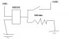
I'v installed a switch on one of the pins of my 16F628A micro with 10K pull down resistor (the switch, when activated pulls up)
The thing is that once the pin is high and i turn off the switch, it doesn't seem to get down at all, but it does when i short circuit the resistor
I'm powering the whole thing from the usb port and i'm driving a very small
5VDC relay (maybe some power problem?)

Any ideas? What do you suggest? Thanks
 
Hi,

Its 10K to Pull UP, 1K to Pull Down.

i put a 1k and still, i even tried to use it to pull-up and couldn't
removed the relay and same story
 

Attachments

  • untitled.JPG
    untitled.JPG
    8 KB · Views: 519
If you're using a PORTB (RBn) pin make sure the internal weak pull-ups are disabled in software.

Which pin are you using? Depending on the PIC, some pins may be TTL-level, CMOS-level, or Schmitt triggers.

Also, make sure you have the pin configured as an input and not an output, and if it's a pin that can be analog (A/D or comparator), that it's set to be digital.

Stick a voltmeter on the pin and make sure the pull-up/down is working correctly. Also, if you can post your code that will help us determine if the pin is configured correctly, the software is reading it correctly, etc.
 
Last edited:
the code is pretty big with many co-working functions (that is you have to read over 500 lines code to know what's going on ;) )
but plz, elaborate on disabling the internal pull-ups, i've never configured those before since i wasn't even aware of them so i most probably have badly configured pins

can you please give me all the steps to making this work with an analog pin? (disabling A/D conversion...)

Thanks
 
From the PIC16F628A datasheet:


PORTA (example shows setting RA4-0 as inputs):
Code:
  CLRF PORTA ;Initialize PORTA by
                            ;setting output data latches
 MOVLW 0x07 ;Turn comparators off and
 MOVWF CMCON ;enable pins for I/O functions
 BCF STATUS, RP1
 BSF STATUS, RP0 ;Select Bank1
 MOVLW 0x1F ;Value used to initialize data direction
 MOVWF TRISA ;Set RA<4:0> as inputs

PORTB (example shows setting RB4-0 as inputs):
Code:
  CLRF PORTB ;Initialize PORTB by
                            ;setting output data latches
 BCF STATUS, RP1
 BSF STATUS, RP0 ;Select Bank1
 MOVLW 0x1F ;Value used to initialize data direction
 MOVWF TRISB ;Set RB<4:0> as inputs
 BCF OPTION, NOT_RPBU  ; Enable weak pull-ups
 BSF OPTION, NOT_RPBU  ; Disable weak pull-ups

Thinking about your issue though, it could be that the pin you're using is configured as an output instead of an input.

Which pin are you using for your input? Have you measured the voltage at the pin? Is it behaving the way you expect with the resistors in place?
 
Hi Nigel,

Its 10K to Pull UP, 1K to Pull Down

Sorry, but where did you imagine that from?.
__________________

Appreciate everything can be calculated individually, but as a general guide for digital / micro testing how are those values so wrong ..?

( trennonix didn't say , and still hasn't said, which port he was using )
 
sorry for replying so late Wp100, but i'm using RB7
thanks Kpatz for that piece of code which i'll try right away
btw in order to switch between banks i only use bsf\bcf STATUS, RP0
i've never used RP1, could that be causing some problems, maybe none that i was able to detect?

Kpatz, your code didn't compile, i had to use OPTION_REG instead of OPTION (just so you'd know)
 
Last edited:
The only time you need to set RP1 in the PIC you're using is to access the last 48 bytes of general purpose registers. See page 18 of the datasheet for the memory map.

But it's generally better to use the banksel directive instead of setting the RP0/RP1 bits manually, since then the assembler/linker will figure out the correct bank for the label/register you're using.

For example:

Code:
  banksel OPTION_REG  ; Select bank where OPTION_REG resides
  ; put something into W here
  movwf  OPTION_REG  ; and set OPTION_REG

Code:
  banksel TRISB  ; Select bank where TRISB resides
  bcf TRISB,RB1  ; make RB1 an output

Code:
  banksel ONE_OF_YOUR_VARIABLES  ; Select bank where your register is
  movfw  ONE_OF_YOUR_VARIABLES  ; Move your register into W

And yes, I get mixed up on OPTION vs. OPTION_REG sometimes. The assembler expects OPTION_REG, but the datasheets often call it just the OPTION register.

Here's my examples, corrected and updated to use banksel:

Code:
 BANKSEL PORTA  ; Select PORTA bank (bank 0, assembler determines which bank and puts in the appropriate BCF/BSF instructions)
  CLRF PORTA ;Initialize PORTA by
                            ;setting output data latches
 ; CMCON is in the same bank as PORTA so no need for a BANKSEL here
 MOVLW 0x07 ;Turn comparators off and
 MOVWF CMCON ;enable pins for I/O functions
 BANKSEL TRISA;  Selects bank 1 (assembler determines which bank and puts in the appropriate BCF/BSF instructions)
 MOVLW 0x1F ;Value used to initialize data direction
 MOVWF TRISA ;Set RA<4:0> as inputs

PORTB (example shows setting RB4-0 as inputs):
Code:
 BANKSEL PORTB  ; Select PORTB's bank (bank 0, assembler determines which bank and puts in the appropriate BCF/BSF instructions)
 CLRF PORTB ;Initialize PORTB by
                            ;setting output data latches
 BANKSEL TRISB;  Selects bank 1 (assembler determines which bank and puts in the appropriate BCF/BSF instructions)
 MOVLW 0x1F ;Value used to initialize data direction
 MOVWF TRISB ;Set RB<4:0> as inputs
 ; Option_Reg is in same bank as TRISB so no banksel needed here
 BCF OPTION_REG, NOT_RPBU  ; Enable weak pull-ups
 BSF OPTION_REG, NOT_RPBU  ; Disable weak pull-ups
 
Last edited:
after adding your code, the serial port stopped working, but when i added external pull down resistors, it worked; so the code is fine
but i'm still having trouble with that switch, like i said before, the whole thing works ok after i short the resistor so it couldn't be a bug


just measured the voltage and got 5V on the resistor, their might a continuous flow of current because i know that the resistor is not damaged (reminding i'm using a 10K resistor)
 
Last edited:
just measured the voltage and got 5V on the resistor, their might a continuous flow of current because i know that the resistor is not damaged (reminding i'm using a 10K resistor)
Is that with the switch open or closed?

With the switch closed, the voltage on the pin should be 5V (through the switch), and with it open, it should be 0 (through the pull-down resistor). With the switch closed, there will be current flowing from +5V through the switch and resistor to ground (about 500 microamps or 0.5 mA according to Ohm's Law). No current should flow in or out of the pin itself, unless the pin is configured as an output, in which case you'll get lots of current if the switch is closed and the pin is set to low (this is why you should have a resistor on the switch side too, to avoid damaging the PIC due to a coding error). If the internal weak pull-ups are enabled, you'll get a small current flow with the switch open, through the weak pullup and your pulldown, and the voltage on the pin will be somewhere in between 0 and 5V, probably somewhere in that in-between never-neverland.

If the pin is 5V with the switch open, you have the pin configured as an output. Check RB7 in the TRISB register, make sure it's set to 1 to make the pin an input. Use the MPLAB SIM debugger to make sure.

What pin is the serial port on?
 
Last edited:
you're right it was set as output! How could i've missed that?!
When I spend so much time on a project these things happen to me alot.
hell, these kinds of mistakes screw up my math grades bad
oh well, at least this is working now
Thanks man

i didn't think that it could be this, because it worked when i shorted the resistor and the state changed when i activated the switch
 
Last edited:
Appreciate everything can be calculated individually, but as a general guide for digital / micro testing how are those values so wrong ..?

Both MUCH lower than would normally be used, and why different values for UP and DOWN? - as well as that, if anything, the pull-up would be the lower value of the two, the pull down is far less important.
 
you're right it was set as output! How could i've missed that?! ...

i didn't think that it could be this, because it worked when i shorted the resistor and the state changed when i activated the switch
When you read a pin, it reads the current voltage on the pin. If the pin is set to output, it's putting out a voltage, and if you read a pin set as output, it reads the voltage which (normally) is what the PIC is outputting, but if you short the pin to Vdd or ground you're forcing the pin high or low regardless of what it's trying to output, so it'll still appear to work as an input, but you'll be sourcing or sinking a lot of current through that pin, and risking damage to the PIC.
 
Status
Not open for further replies.

Latest threads

New Articles From Microcontroller Tips

Back
Top