Continue to Site

Welcome to our site!

Electro Tech is an online community (with over 170,000 members) who enjoy talking about and building electronic circuits, projects and gadgets. To participate you need to register. Registration is free. Click here to register now.

  • Welcome to our site! Electro Tech is an online community (with over 170,000 members) who enjoy talking about and building electronic circuits, projects and gadgets. To participate you need to register. Registration is free. Click here to register now.

Pull-Type Solenoid Controller

Status
Not open for further replies.

Electric Rain

New Member
I need a little bit of help, and it shouldn’t be too hard… I am going to be using pull-type solenoids for a project of mine. I am going to mount two of these solenoids on opposite ends of a light switch. I will be using IR communication too. I will use the following IR Transmitter and Receiver,:


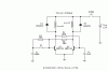
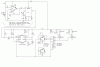
to activate these solenoids. Both solenoids will be attached to the switch (on opposite ends like I said) by… a string or something. And the transmitter part of the circuit will consist of a NO push-button switch. So my question is, how can I make the receiver part alternate between turning one solenoid on or the other? So, if the light attached to the wall switch is on, and the push-button switch is pressed, the bottom pull solenoid will activate, pulling the switch down, thus, turning the light off. However, if the SAME push-button switch is pressed again, the top pull solenoid will activate, pulling the switch up, and turning the light on. Then when it’s pressed again, the bottom one will activate and so on. I would like to know how to build the alternating part of the circuit WITHOUT using power when the solenoids aren’t active. Can someone help me please? Thanks.

Electric Rain
 
Hi Electric Rain,

well, since the Infra-Red receiver will need to have a
supply to operate, it would seem that a flip-flop in
that area should suit you.

The Infra-Red red receiver would have to be supplied
however, during the time the solenoids are inactive,
in case you want to turn the light on, or if you want
to turn it off. But they take very little current in
the 'standby' condition.

Best of luck with it,
John :)
 
It there any way that you could provide me with a schematic please? :) Thanks.

Rain
 
:x
The simple way is to put another switch in parallel with the main one.
This switch will put to switch one wire from one soleno to another, and if you make correct links, the solenoids will be powered as you wish.
As you can view, no need for power because no electronics involved.
 
Ron H said:
Mr. Rain, how much current does each solenoid draw?
The reason I'm asking is that I will draw you a schematic if you answer the question.
 
:lol:
Here is a circuit that can be used.
**broken link removed**

The S1 is put in parallel with the main switch and is closed in one position of the electromagnets rod and is open into second position.
The S2 is your push botton for powered and master switch.
When S2 is pushed, the circuit is powered and the coil1 or coil2 will be powered function of the position of S1. Coil1 and coil2 are two small relays that powered your main electromangets.
How circuit work.
When the 2 transistors bistable is powered, allways the faster transistor will go into ON state and the slower into OFF state. One transistor can be slow down by using one capacitor into it base. When S1 is open the Q1 is faster transistor and the coil1 will be powered, when S1 is close the Q1 is the slower transistor, and the coil2 will be powered.
 

Attachments

  • coils2.GIF
    coils2.GIF
    4.3 KB · Views: 337
I can't vouch for the receiver portion of the circuit, and I haven't tested or simulated the part I added, but here's what it's intended to do:

The LM567 has an open collector output that goes low when a signal is detected. This triggers the 555 monostable, which puts out a 110ms positive pulse. Each time the 555 is triggered, the flip-flop changes state. The AND gates steer the 110ms pulse alternately to the two MOSFET gates. This pulls in a solenoid for 110ms, which should be long enough to change the position of your mechanical switch. I don't think you want to leave the solenoid on indefinitely, since it draws almost 4 amps and is rated for intermittent duty. You can play with how long the solenoids stay pulled in by changing R3 and/or C3.
 

Attachments

  • solenoid_driver1.GIF
    solenoid_driver1.GIF
    13.9 KB · Views: 328
Status
Not open for further replies.

Latest threads

New Articles From Microcontroller Tips

Back
Top