romeshkumar
New Member
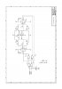
I am very interested in electronics and I have build few basic circuits. I have attached a circuit that I am trying to understand and I need some help. The inputs to the NOR gate PEL1.PWM and PEL1.DIR comes from the micrcontroller AT90CAN128 and they have a pull down resistor to GND. Just curious to know what will happen if I output a 1 or 0 on the GPIO pins of the micro and why do we need the pull down resistor at that place.
Thanks a lot
Thanks a lot

")
