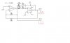
I simmed this in LTSpice and found two things: The units for the capacitor are not given in the original schematic; I found that 1uF or 0.1uF worked OK; and 2) I needed to use +15VDC and -15VDC to make it work. However, I was using a TL072 model instead of TL082, but it should otherwise be the same.
Hope that helps,
Torben


")