Continue to Site

Welcome to our site!

Electro Tech is an online community (with over 170,000 members) who enjoy talking about and building electronic circuits, projects and gadgets. To participate you need to register. Registration is free. Click here to register now.

  • Welcome to our site! Electro Tech is an online community (with over 170,000 members) who enjoy talking about and building electronic circuits, projects and gadgets. To participate you need to register. Registration is free. Click here to register now.

Proteus power pin

Status
Not open for further replies.

bluestar.unni

New Member
hi,

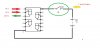
I need help to create my hobby circuit. In this circuit i want to switch ON a 555 ic only if some specific conditions met. so i want to connect the power pin of ic to a relay\switch. how it is possible since the power pin is hidden?? :confused: (the relay/switch will automatically controlled by external circuit so don't worried about it )
 
hi,
Are you saying the VCC pin of the 555 timer is not showing on the 555 symbol.??
 
The NE555 part in the analog library has the Vcc pin and a spice model.
 
The 555 has a "reset" pin that will work for you based on the limited info you've provided.

How do you envision the 555 performing? One shot? Retriggerable monostable? Oscillator?
 
Right click on the gate, edit properties, then select hidden pins.

You can type in a specific net name for the IC's GND and VCC pins.

To create new power rails, go design -> Configure Power rails. Here you can create new power nets of any voltage, and connect the net names used for your IC's to them.

Hope that helps!
 
thank you Rich, i got it (check 'POWER PIN.DSN' ). but i want the circuit as in the attachment 'power pin switch.JPG' please check it & help !
 

Attachments

  • power pin switch.JPG
    power pin switch.JPG
    56.1 KB · Views: 1,015
  • POWER PIN.zip
    3.2 KB · Views: 537
I guess you are trying to enable some logic only on a certain condition, classical methods in my opinion would be a far more suitable option, such as using reset pins of IC's, gating signals (with and gates, although asynchronous methods would make most digital engineers shudder) or by doing proper synchronous logic with some kind of idle state or synchronous gating.

Anyway, not sure how to do such a thing, Proteus naturally infers any hidden VCC pin of an IC as power net and I am not sure how to change that. It's the common way, in every design I have worked on, all the IC's are hooked up to their respective rails at all times and control signals are used to determine if other IC's are enabled or not.

If you still wish to go this route and are interested in PCB design rather than simulation in ISIS, create your own symbols to match your needs, or place your relay contacts between power terminals. A specific VCC net for your logic IC, and VCC. In real life, the rails will not exhibit their respective voltages and hence do not need worrying about.
 
Status
Not open for further replies.

Latest threads

New Articles From Microcontroller Tips

Back
Top