Continue to Site

Welcome to our site!

Electro Tech is an online community (with over 170,000 members) who enjoy talking about and building electronic circuits, projects and gadgets. To participate you need to register. Registration is free. Click here to register now.

  • Welcome to our site! Electro Tech is an online community (with over 170,000 members) who enjoy talking about and building electronic circuits, projects and gadgets. To participate you need to register. Registration is free. Click here to register now.

proteus 741 op amp current to voltage help

Status
Not open for further replies.
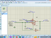
Your schematic in post #12 still has the non-inverting and inverting input tied to ground which is useless.

the other problem is the equation for the standard I-V converter is Vout = -I*Rf. Note the inversion. That's a potential problem.

Now, You can put the non-inverting input at some value, Vb, and the transfer function becomes Vout=Vb-I*Rf. Hence the questions of what does 2.5mA have to map to?

There is usually a capacitor across the feedback resistor for stability and to limit bandwidth.

The two most important parameters for an I-V converter is Vos and Ib and it's temperature dependence. I built a 4-terminal I-V converter that had +-10V outputs for 4 decade ranges lower than +-100 mA. It was biasable (+-10V) and had suppression of +-50mA. I needed AC performance and I was not allowed the time to tweak the DC performance that I had planned. It ended up having 40pA of offset.
 
Now it looks like the analog circuit must produce an output of +2..0V when the input is -2.5mA.
It must produce an output of +2.5V when the input is 0mA.
it must produce an output of 3.0V when the input is +2.5V.
And all voltages and currents in between.
Is this what the analog circuit should do before the lowpass filter?

Then the A to D converter has an input from +2.0V to +3.0V?

Why not ask your teacher instead of us guessing about it in this forum?
ok so am i to use the formula R1 = VoMax - VoMin/IinMax - IiMin
= 3-2/0.0025 - -0.0025 = 200 ohms

so i need a Rf 200 ohms and a positive 2.5 v to pin 3 ?
 
If you look at Kiss's comment.... Both inputs are ground... So nothing will work.. The inputs should at least be centered around 2.5V using potential dividers..
so 5v at pin 7 and -5 at pin 4 , then use a potenial divider and supply 2.5v to pin 3 ?
 
Actually ... You will need an offset... I'm not the best guy to ask.. I can help with proteus, but others can help with the opamp.

I'm not sure ( without checking ) if a potential divider on the input will allow -2.5mA...
 
Actually ... You will need an offset... I'm not the best guy to ask.. I can help with proteus, but others can help with the opamp.

I'm not sure ( without checking ) if a potential divider on the input will allow -2.5mA...
ok thanks so far ian i do have a question on proteus in my circuit below we can see that pin 2 of the op amp is drawing current when it should be going to the resistor ?
 

Attachments

  • new idea.png
    new idea.png
    102.1 KB · Views: 286
Hey, the ground is removed. Yippie.

Should you look at the output with a scope probe?
Or look at it with DC inputs of -2.5mA and +2.5mA?
 
Your "new idea" has the input grounded instead of as a current input and you biased the opamp with +2.5V then it will try to amplify the 2,5V two hundred thousand times to +50 thousand volts! But its maximum output with your +/-5V supply is 4V as shown in your simulation.
 
Hey, the ground is removed. Yippie.

Should you look at the output with a scope probe?
Or look at it with DC inputs of -2.5mA and +2.5mA?
ok so i used a volt meter and at 2.5mA the output decreased from 2.5v to 2v then started to increase
the same for - 2.5mA it increased the output from 2.5v to 3v and then started to decrease. i know a capacitor can be used to stable the circuit
using the formula c1= 1/2pi x r1 x fp = 1/2pi x 200 x 0.01= 0.079 = 0.08 picofarads?
 

Attachments

  • idea update.png
    idea update.png
    103.6 KB · Views: 281
Your "new idea" has the input grounded instead of as a current input and you biased the opamp with +2.5V then it will try to amplify the 2,5V two hundred thousand times to +50 thousand volts! But its maximum output with your +/-5V supply is 4V as shown in your simulation.
am i going the right way now , im using a +/-15v supply and the output does not go over 3 V
 
We need to knock some sense in your head. I'll try.

You should not input a sine wave current source and look at the DC out.
Since this circuit is expected to amplify AC, the output will be DC+AC and be the right output if the probe is DC coupled.

The circuit does respond to DC, so use a DC current in and measure a DC voltage out at -2.5mA, 0mA and 2.5mA.

In the real word, there is an input offset voltage which also gets added to your DC value at the + input. So, zero V in wont give you the expected value. I have no idea if that shows up in simulation.

You do need to put a capacitor across the feedback resistor, it's a real word requirement. You should see the effects in simulation.
Good old fc=1/(2*PI*R*C); Fc is the -3db frequency. The output is down 70.7% at that frequency. Fc has to higher than the frequency of interest.

Real world requires bypass capacitors, but you don't need them in simulation.
 
Your capacitor calculation shows 0.08pF which is extremely tiny and wrong. The correct calculation results in 0.08 Farads which is 80mF which is 80000uF.
Your 0.01Hz frequency is one wave every 100 seconds. I removed the useless capacitor. Your voltage slowly changed because you probably use a Mickey Mouse solderless breadboard with poor connections and wires all over the place as antennas that pickup interference.

Your current source also needs the same +2.5V offset voltage as the opamp.
I show your circuit with an input from -2.5mA to +2.5mA and it has an output from +2.0V to +3.0V. Is that what you want?
 

Attachments

  • current to voltage.png
    current to voltage.png
    51 KB · Views: 264
We need to knock some sense in your head. I'll try.

You should not input a sine wave current source and look at the DC out.
Since this circuit is expected to amplify AC, the output will be DC+AC and be the right output if the probe is DC coupled.

The circuit does respond to DC, so use a DC current in and measure a DC voltage out at -2.5mA, 0mA and 2.5mA.

In the real word, there is an input offset voltage which also gets added to your DC value at the + input. So, zero V in wont give you the expected value. I have no idea if that shows up in simulation.

You do need to put a capacitor across the feedback resistor, it's a real word requirement. You should see the effects in simulation.
Good old fc=1/(2*PI*R*C); Fc is the -3db frequency. The output is down 70.7% at that frequency. Fc has to higher than the frequency of interest.

Real world requires bypass capacitors, but you don't need them in simulation.
ok i think i have it now
-2.5mA =2v
0 = 2.5v
2.5mA = 3v

ok ive completed my circuit, the input corresponds correctly with voltage output i used 2 resistors to achieve 2.5v for pin 3. my final question is what reasoning do i use for choosing them why not say two 470k resistors instead of two 10 k resistors. i plan to run the output through a low pass filter of 50Hz again i know the formula but how do i choose a realistic value for resistor ?

1620155274951.png
 
In the real world, a divider to the 5V supply is a BAD idea, because the 5V supply isn't 5V. It could be 4.95 or 5.1. It varies +-10% "off the shelf".
That's the tolerance of the regulator. It also varies with temperature and with 'dynamic load". It's not a reference. On paper, maybe.

Unfortunately, the impeadance of what feeds the OP-amp inputs, a lot of times has to be low. So, you might be able to use 10K and 10K, but they are +-5%. You may have to buffer that with a unity gain buffer.

That's exactly how one guy at worked designed a converter, but he used a 5V reference and created a -5V reference with an inverting buffer. Then placed a potentiometer between the +-5V and then buffered the wiper and fed that to the non-inverting input. So that point could be +-5V.

That's the way it should be done.

A summing amplifier won't work unless the inputs have a very low impeadance,

Watch the concept of noise gain: https://www.electronicdesign.com/te...801225/whats-all-this-noise-gain-stuff-anyhow

The I-V converter should use an OP-amp that is unity gain stable.
 
You wrongly show your input current source at ground instead of at the required +2.5V offset voltage.

The values of the voltage divider resistors depend on the maximum input bias current of the opamp. The very old 741 opamp has a max input bias current of 0.5uA so if the resistors have a current of 25uA then the 2.5V will be changed 10% max.
5V/25uA= 200k ohms. The 2.5V will change 5% max with 100k resistors.

Your capacitor is huge. Do you have a frequency as low as 0.01Hz which is one fullwave every 100 seconds?

Why do you need a 50Hz lowpass filter when the input signal is 0.01Hz?
The filter resistor value should be 1/20th the filter's load resistance for a 5% DC voltage drop.
 
You wrongly show your input current source at ground instead of at the required +2.5V offset voltage.

His current source is fine. If (+) is at 2.5. then his source will be at 2.5V with the OP amp doing it's thing. it's OK, it just looks a little weird.

Let's say that the output signal is not in phase with the input, but the required amplitude is correct. That's a problem between the way the problem is written and interpreted.

I can't tell the value of C1. If it's 80uF that's to big. mF or milli-Farad we never see because it can get confused with early nomenclature. MF and MFD or even MMFD.

This https://www.vishay.com/capacitors/volt-10-25/capacitance-1mf-greater/ page is wierd. It has mF units.
 
Last edited:
I can't tell the value of C1. If it's 80uF that's to big.
He uses the extremely low frequency of 0.01Hz in his calculation. With the 200 ohms resistor, the capacitor value is 80000uF which is 80mF.
One milli is 1000 micros.

I posted this in the other forum:
 

Attachments

  • current to voltage.png
    current to voltage.png
    51 KB · Views: 255
Status
Not open for further replies.

Latest threads

New Articles From Microcontroller Tips

Back
Top