Continue to Site

Welcome to our site!

Electro Tech is an online community (with over 170,000 members) who enjoy talking about and building electronic circuits, projects and gadgets. To participate you need to register. Registration is free. Click here to register now.

  • Welcome to our site! Electro Tech is an online community (with over 170,000 members) who enjoy talking about and building electronic circuits, projects and gadgets. To participate you need to register. Registration is free. Click here to register now.

proteus 741 op amp current to voltage help

Status
Not open for further replies.

grc26278

New Member
recently new to op amps , for my classwork ive been asked to use a 741 op amp to convert a current ac signal in the range of -2.5 to 2.5 mA to a voltage signal in the range of 2 to 3 volts. below i have attached the circuit in Proteus im unsure if im correct and which formula to use to calculate the resistor value needed.
 

Attachments

  • op amp 1.png
    op amp 1.png
    94.9 KB · Views: 1,833
What good does shorting both inputs of the OP amp to ground do?

In the range of 2-3 V is different than say [-2.5 mA to 2V and 2.5 mA to 3 V] and [-2.5 mA to 3V and 2.5 mA to 2 V]

BTW, the 741 is a really bad OP-amp for that function and I believe the 741 has to have a dual supply.
 
Last edited:
What current is supposed to correspond to 2V out and what current corresponds to 3V out?
 
maybe he wants 2volts offset
If you look at Kiss's comment.... Both inputs are ground... So nothing will work.. The inputs should at least be centered around 2.5V using potential dividers..
 
What good does shorting both inputs of the OP amp to ground do?

In the range of 2-3 V is different than say [-2.5 mA to 2V and 2.5 mA to 3 V] and [-2.5 mA to 3V and 2.5 mA to 2 V]

BTW, the 741 is a really bad OP-amp for that function and I believe the 741 has to have a dual supply.
is there an op amp you know of in proteus that would be better suited ?
 
What current is supposed to correspond to 2V out and what current corresponds to 3V out?
it has to be within that range so i can choose in between -2.5 and 2.5 mA , so for example i choose 2mA input and want 2.5 volts output , im unsure on what formula to use to find resistor value needed
 
is there an op amp you know of in proteus that would be better suited ?
The 741 will do what you want... BUT! first apply 5 volts to pin 7 and -5 to pin4... Then work out the amplification..
 
You said AC and you said 741 opamp.
AC has frequencies and the 741 opamp design is 53 years old and has a severe fairly low frequency limit.

Did you learn Ohms Law that says a current can be measured by measuring the voltage across a low value series resistor?
Did you learn how an opamp can measure and amplify a voltage?
yes , the full question in class work is "a remote speed sensor provides a current signal in the range of -2.5 to 2.5 mA and a frequency of 0.01 Hz design an op amp circuit to convert this ac signal to the required output voltage of 2 to 3 V. The finished circuit is then to be combined to a low pass circuit filter to supress any noise above 50hz"
 
2.5mA in a 1k resistor produces 2.5V. Then the opamp can be a simple lowpass filter.
 
The 741 will do what you want... BUT! first apply 5 volts to pin 7 and -5 to pin4... Then work out the amplification..
ok so i think im nearly there i used battery's to supply a negative and positive voltage to pins 4 and 7 , my understanding is Rf = Vout/Iin. so if i have a supply of 2.5 mA and want an output of 2 V i can use the formula 2/0.0025 = 800 therefore an resistor of 800 ohms is need for required output. as the voltage probe shows this is not the case am i missing another resistor and using an incorrect fromula
 

Attachments

  • proteus new.png
    proteus new.png
    101.1 KB · Views: 408
The datasheet for the antique 741 opamp shows its specs only when its powered by +15V and -15V.
Your opamp's inverting input is grounded then it does nothing. The inverting input is its +/-2.5mA input.

Do you know how to make the inverting opamp a lowpass filter?
 
The datasheet for the antique 741 opamp shows its specs only when its powered by +15V and -15V.
Your opamp's inverting input is grounded then it does nothing. The inverting input is its +/-2.5mA input.

Do you know how to make the inverting opamp a lowpass filter?
so youre saying my generator should be connected to pin 3 instead ? this is an example i have been shown. as for low pass filter i will run the output into a 1k resistor then a 3.2 micro farad capacitor connected to ground. i used the formula c = 1/2 Rfcutoff. = 1/2x1000x50 = 3.18 my only question about this is how do i workout the size of resistor to use as i just used 1 k to work out the formula or is 1k resistor fine ?
 

Attachments

  • voltage amp example.png
    voltage amp example.png
    22.6 KB · Views: 356
So you're saying my generator should be connected to pin 3 instead?
No. I said the inverting input which is pin 2 and the 800 ohms resistor but no RS input resistor. When the inverting input has +2.5mA then the output of the opamp will go negative with 2.5mA in the 800 ohms resistor which is -2V. When the inverting input has -2.5mA then the output of the opamp will go to +2V.


This is an example I have been shown.
It is wrong with a voltage input instead of a current input. Does your generator have a current output of +2.5mA and -2.5mA?

As for low pass filter I will run the output into a 1k resistor then a 3.2 micro farad capacitor connected to ground. i used the formula c = 1/2 Rfcutoff. = 1/2x1000x50 = 3.18 my only question about this is how do i workout the size of resistor to use as i just used 1 k to work out the formula or is 1k resistor fine?
That will be fine if the load is a high resistance.
 
Last edited:
No. I said the inverting input which is pin 2 and the 800 ohms resistor but no RS input resistor. When the inverting input has +2.5mA then the output of the opamp will go negative with 2.5mA in the 800 ohms resistor which is -2V. When the inverting input has -2.5mA then the output of the opamp will go to +2V.


It is wrong with a voltage input instead of a current input. Does your generator have a current output of +2.5mA and -2.5mA?

As for low pass filter I will run the output into a 1k resistor then a 3.2 micro farad capacitor connected to ground. i used the formula c = 1/2 Rfcutoff. = 1/2x1000x50 = 3.18 my only question about this is how do i workout the size of resistor to use as i just used 1 k to work out the formula or is 1k resistor fine?
That will be fine if the load is a high resistance.
[/QUOTE]
ok thanks i appreciate the help so far , as for for the current outputs that has me unsure , the complete circuit output is to be connected to a circuit that has an 8-bit counter with a 4-to-7 decoder which has a seven segment display. it has been suggested that i change values of the input generator to show different values on the segment display so that has me thinking -2.5 mA needs an output of 2v and 2.5 mA has an output of 3v
 
The simple current input to voltage output opamp has a positive and negative output. You never said a positive only output.
The digital circuit must not have a negative input. Also it needs a logic input voltage higher than 2V.
Now your entire project makes no sense.
 
The simple current input to voltage output opamp has a positive and negative output. You never said a positive only output.
The digital circuit must not have a negative input. Also it needs a logic input voltage higher than 2V.
Now your entire project makes no sense.
ok full detail of project is as follows
Detail of the task
Analogue:

A remote motor speed sensor provides a current signal in the range of -2.5 to 2.5 mA. Design a circuit to convert this signal into a voltage signal in the range from 2 to 3 V. After the conversion, a low pass filter is used to suppress any noise AC signals with frequency higher than 50 Hz.


Digital:

An 8-bit analogue-to-digital converter will be given and should be used to convert the output of the above analogue circuit into an 8-bit digital signal. The 8-bit signal should go through two 4-to-7 decoders so that the value of the 8-bit digital signal is displayed as two hexadecimal values on two seven-segment display devices to indicate the safe running speed of the motor in range 0-255 (i.e. 00hex to FFhex).


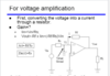
Part 1: Design a current amplification and filtering circuit [40 marks]
Use an AC current source with a very low frequency of 0.01 Hz to emulate the slowly changed current output signal from the remote motor speed sensor. Design the current amplification circuit using appropriate op-amp circuits so that you can achieve the required output voltage (2 to 3 V). Demonstrate the gain, Bandwidth, Rin of your op-amp circuits by both calculation and simulation.


Design the low-pass filter. Demonstrate the bandwidth of the filter by both calculation and simulation.


Combine the op-amp circuit and the filter. Demonstrate the gain, Bandwidth, phase shift, Rin of your combined circuit by both calculation and simulation.


Marks allocation:

  • Current sampling/amplification circuit: [15 marks]
  • Low-pass filter circuit: [15 marks]
  • Combined circuit: [10 marks]


Part 2: Design an 8-bit counter and a 4-to-7 decoder for the Seven-Segment display [40 marks]
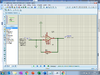
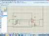
The output voltage signal from the analogue circuit should then be converted into an 8-bit digital signal, which represents the levels of the motor speed. You can choose the generic 8-bit ADC device from the Proteus library => Modelling Primitives => ADC_8 for this task. Following is an example connection of the ADC convertor that you can refer to when you design your circuit.


2.1) 8-bit counter design
Design an 8-bit synchronous counter by using D-type flip-flops. The counter should be driven by a CLK signal running at 256k Hz. You should show how the counter is designed, and simulate the circuit.


Marks allocation: [15 marks]


The MSB output of the counter should be used to connect to the clock terminal of ADC_8 converter. The value of the output of the ADC_8 converter should be displayed in two 7-segment display units. The MSB four bits are displayed in one and the LSB four bits in another 7-segment display. In order to achieve this, you should design the 4-to-7 decoder for the 7-segment display, as detailed below.


2.2) 4-to-7 decoder design
A 7-segment display decoder is commonly used to display a particular number representation using a display composed of seven LED segments. The diagram below represents a 7-segment display decoder which converts a 4-bit binary number into a collection of symbols to be displayed:


Your 7-segment decoder should accept a 4-bit binary numbers [x3, x2, x1, x0], which represent integer numbers 0 - 9 and letter A, B, C, D, E, F (i.e. which represent hexadecimal value in range 0hex to Fhex). A 7-segment display with common anode should be used, i.e. the decoder should output “0” to switch on the corresponding LED segment (a-g) of a 7-segment display shown above. The symbols used should be:


Complete the truth table for the 4-to-7 decoder: Use Karnaugh map to simplify the logic expressions for the 4-to-7 decoder. You can use all available gates (some of them are listed below). Simulate your decoder circuit and demonstrate that the circuit is working properly.


Marks allocation: [15 marks]


2.3) Combined digital circuit
Connect the outputs of the 8-bit ADC to two 4-to-7 decoders which drive two seven-segment display units, respectively. Simulate the circuit and demonstrate that entire circuit works properly.


Marks allocation: [10 marks]
 
Now it looks like the analog circuit must produce an output of +2..0V when the input is -2.5mA.
It must produce an output of +2.5V when the input is 0mA.
it must produce an output of 3.0V when the input is +2.5V.
And all voltages and currents in between.
Is this what the analog circuit should do before the lowpass filter?

Then the A to D converter has an input from +2.0V to +3.0V?

Why not ask your teacher instead of us guessing about it in this forum?
 
Status
Not open for further replies.

Latest threads

New Articles From Microcontroller Tips

Back
Top