Hi all,
I'm new to this forum.
I've just started dipping my toes into the electron stream and it's not as easy as I thought it was.
I'm a technical guy (web designer) but I've gotten lost on my project. Can you help?
I've got a small mono amp operating on 9 volts. It has a sound input which is powered by the amp – about 1.2v. It then outputs to a 1 watt 8 ohm speaker. This all works perfectly.
Now, what I want to do is connect the output of the amp to a voice recorder circuit. The voice recorder is designed to play a sound only (we use the VR because we can record funny sounds on it). It has a momentary switch which plays the digitised sound. I hooked up the amp output to the momentary switch input and got the voice recorder to make the digitised sound based on the amount of voltage being generated by the amp. The DC voltage is 0.00 and the AC runs between 0.00 and 600mV depending on it the output from the amp.
Here's what we want to do:
When the sound plays (active AC voltage) we don't want the voice recorder circuit to play any sounds.
When the amp stops outputting sound (no AC voltage) or the voltage drops below a certain threshold, we want it to trigger the voice recorder and play it's digitised sound (probably a fart sound or something). The VR sample will run for about 1 to 2 seconds.
I know this should be simple but I just can't get my head around it. Not sure if the voltage needs converting to DC and then storing in a capacitor to release when the voltage drops (no sound from amp). That way could it make a momentary circuit?
So, to recap. There are two circuits:
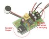
1 watt mono amp – operates between 4.5v and 9v.
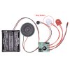
20 second voice recorder which has a built in mic and speaker – operates between 4.5v and 6v.
Then there is the external speaker for the amp and an input – either a mic or an mp3 player.
My electronics knowledge is basic so any help would be most welcome. Treat me gently though because my knowledge does not extend very far. This is a project for my kids – I promised I would do it!
Here's hoping,
Rees.
I'm new to this forum.
I've just started dipping my toes into the electron stream and it's not as easy as I thought it was.
I'm a technical guy (web designer) but I've gotten lost on my project. Can you help?
I've got a small mono amp operating on 9 volts. It has a sound input which is powered by the amp – about 1.2v. It then outputs to a 1 watt 8 ohm speaker. This all works perfectly.
Now, what I want to do is connect the output of the amp to a voice recorder circuit. The voice recorder is designed to play a sound only (we use the VR because we can record funny sounds on it). It has a momentary switch which plays the digitised sound. I hooked up the amp output to the momentary switch input and got the voice recorder to make the digitised sound based on the amount of voltage being generated by the amp. The DC voltage is 0.00 and the AC runs between 0.00 and 600mV depending on it the output from the amp.
Here's what we want to do:
When the sound plays (active AC voltage) we don't want the voice recorder circuit to play any sounds.
When the amp stops outputting sound (no AC voltage) or the voltage drops below a certain threshold, we want it to trigger the voice recorder and play it's digitised sound (probably a fart sound or something). The VR sample will run for about 1 to 2 seconds.
I know this should be simple but I just can't get my head around it. Not sure if the voltage needs converting to DC and then storing in a capacitor to release when the voltage drops (no sound from amp). That way could it make a momentary circuit?
So, to recap. There are two circuits:
1 watt mono amp – operates between 4.5v and 9v.
20 second voice recorder which has a built in mic and speaker – operates between 4.5v and 6v.
Then there is the external speaker for the amp and an input – either a mic or an mp3 player.
My electronics knowledge is basic so any help would be most welcome. Treat me gently though because my knowledge does not extend very far. This is a project for my kids – I promised I would do it!
Here's hoping,
Rees.