Continue to Site

Welcome to our site!

Electro Tech is an online community (with over 170,000 members) who enjoy talking about and building electronic circuits, projects and gadgets. To participate you need to register. Registration is free. Click here to register now.

  • Welcome to our site! Electro Tech is an online community (with over 170,000 members) who enjoy talking about and building electronic circuits, projects and gadgets. To participate you need to register. Registration is free. Click here to register now.

Project design help? Remote operation for my adjustable struts

Status
Not open for further replies.

mmc757

New Member
Greetings all! This is my first post so I will get the intro out of the way before getting down to business:
My name is Scott, I am in the Navy, married, 2 teenage daughters, 5 dogs, 2 cats, 1 horse. My electronics background is limited to basic theory for the most part. I have a general understanding of how circuits work, what the purposes of most components are, etc. I have very little experience with actually working on these things though. Pretty much limited to basic home/auto-repair style stuff.

So heres the project I'm looking for some help with:
On my car, I have installed some Koni adjustable struts.
**broken link removed**
What I would like to do is build a system to adjust them remotely, from the drivers seat.

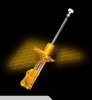
-In the picture, the white knob on top of the strut is the adjustment knob. It slips on and off, and is only used for manual operation.
-The actual piece being operated is a small flat ear similar to a flathead screwdriver tip, about 1/2" wide.
-The range of motion is 2 full turns.
-There is very little torque required. can be done by fingers
-In a perfect world, I would be able to adjust them back and forth from the drivers seat to a minimum of 4 distinct positions, but more would be okay.
-I need to know exactly what position they are in at any given time, so either through switch position or indicator lights would work.
-There are four struts, but they should be operated in groups of two (front and rear separate)
-Space available is very limited

In my attempts so far to figure this out, I am getting the idea a stepping motor might be the way to go, but I am really only guessing. There may very well be a better option out there. I understand that a stepping motor needs some sort of controller, but I'm not really sure how all that would work...
Any thoughts about how to do this?
 

Attachments

  • koni.jpg
    koni.jpg
    53.4 KB · Views: 156
This is not a trivial task.

You could perhaps use a stepper motor such as this with a driver such as this.

But then the question is how to generate the number of steps for the desired motion. A microprocessor would require the least number of parts for this but you would have to learn some programming skills. Otherwise it would require some counters and other logic to generate and keep track of the number of steps, and the direction of motion.
 
Would it be possible for a multi-position switch to be used to send the appropriate signal directly to the controller, so the programming is effectively accomplished by the wiring?
 
Would it be possible for a multi-position switch to be used to send the appropriate signal directly to the controller, so the programming is effectively accomplished by the wiring?
The controller just has two inputs: direction and step. You still need circuitry between the switch and the controller to tell it which direction and how many steps.
 
I see.
What about a regular, low rpm (or geared for low rpm) motor with a time delay relay?
Time the full rotation, then set the TDR to cutout after the desired amount of time. I would have to figure out some other way to indicate position...
 
Last edited:
I see.
What about a regular, low rpm (or geared for low rpm) motor with a time delay relay?
Time the full rotation, then set the TDR to cutout after the desired amount of time. I would have to figure out some other way to indicate position...
You can't accurately control the position by time due to differences in the motors, temperature, voltage, etc. You could perhaps control position by putting one or more micro-switches activated by cam(s) on the motor output shaft. You could have a toggle switch to control direction and a push button to activate the motion. The motor would stop when the next cam position opens the microswitch.

If you wanted an indication of the position you could use an up/down counter circuit driving a display to count the number of cam switch actuations. The counter would count up for one position of the directional control toggle switch and count down for the other position.
 
Last edited:
Amusing: I wonder how simply a quadrature encoder could drive a stepmotor. It would be a digital servo. The rotation angle ratio would be the steps/deg of encoder : stepmotor and modifiable by a divide by n.
You could have a 3 position switch for "front / all / rear" and 7 segment count displays. Of course, a uC & step drivers make it pretty straightforward... <<<)))
 
You can't accurately control the position by time due to differences in the motors, temperature, voltage, etc. You could perhaps control position by putting one or more micro-switches activated by cam(s) on the motor output shaft. You could have a toggle switch to control direction and a push button to activate the motion. The motor would stop when the next cam position opens the microswitch.

If you wanted an indication of the position you could use an up/down counter circuit driving a display to count the number of cam switch actuations. The counter would count up for one position of the directional control toggle switch and count down for the other position.

That makes sense, I was thinking about the problems with timing myself on the way home yesterday.
Are the materials for the cam/microswitches readily available? Also, could those switches be used to activate indicator lights instead? The motor doesnt need to have specific stopping points, as long as I have some sort of indication of where its at, I can just hold the switch until it gets where I want it then let go.

Amusing: I wonder how simply a quadrature encoder could drive a stepmotor. It would be a digital servo. The rotation angle ratio would be the steps/deg of encoder : stepmotor and modifiable by a divide by n.
You could have a 3 position switch for "front / all / rear" and 7 segment count displays. Of course, a uC & step drivers make it pretty straightforward... <<<)))
I feel like I just gone done listening to someone speaking in a heavy scotish accent!:D I understood a little of that, but some of it was a foreign language to me:eek:
I looked up quadrature encoder on wikipedia and I understand what your saying there...use the position sensor to provide the signal to the controller. Would that be possible at a reasonable cost and with only very basic elec. skills?
I assume a uC and stepdrivers are what was discussed earlier that are normally used to control the stepmotor. Is that something I could easily learn how to setup?

Could a servomotor be easily setup to stop at specific points, or would that have the same exact problems were already discussing? It seems like the RC world would already have something like that for airplanes???
 
Last edited:
...In a perfect world, I would be able to adjust them back and forth from the drivers seat to a minimum of 4 distinct positions, but more would be okay...

I was just out walking and it occurred to me that this phrase may be overcomplicating the problem. A simple forward/reverse switch would probably be fine with a low speed rotation as long as I had adequate, reliable position indication...
 
Your hobby servo idea might work. If you could get 3 turns of wire around the shaft then size the lever arm on the servo to get your 2 turns since the servos only rotate about 170 degrees. This would be easy to control with a 1 IC circuit.
 
Your hobby servo idea might work. If you could get 3 turns of wire around the shaft then size the lever arm on the servo to get your 2 turns since the servos only rotate about 170 degrees. This would be easy to control with a 1 IC circuit.

Can you elaborate on the 1 IC circuit?
 
Are the materials for the cam/microswitches readily available? Also, could those switches be used to activate indicator lights instead? The motor doesnt need to have specific stopping points, as long as I have some sort of indication of where its at, I can just hold the switch until it gets where I want it then let go.
A cam could be simply a screw head sticking out of the motor shaft or coupler to engage a microswitch. Microswitches are very common (just Google). Certainly the microswitch could operate a light instead of being a limit switch.

Just holding the control switch would work but you'd need a switch and indicators for each motor since each would move at a slightly different speed. You could use a SPDT momentary toggle switch with center-off. That way you only need one switch to control both on-off and direction.

The tricky part for an indicator is that you want to go two turns, so you need some way of counting turns.
 
The hobby servos are controlled by sending a pulse between about 1 ms to 2 ms. Less than 1.5 ms moves one direction, greater than 1.5 moves in the other direction. This circuit (2nd one) would let you turn a knob to set the position.

SERVO TESTER Circuit
 
Would this be doable?: A servomotor with a rack and pinion style gearset to drive both the adjusting screw and a series of microswitches to actuate indicator lights.
 
Would this be doable?: A servomotor with a rack and pinion style gearset to drive both the adjusting screw and a series of microswitches to actuate indicator lights.
That would work but how will you keep track of two revolutions? You could, of course use a 2:1 reduction from the adjusting screw position so that the sense cam would move one revolution for the two shaft revolutions. Perhaps some type of hobby gears would work for that.
 
That would work but how will you keep track of two revolutions? You could, of course use a 2:1 reduction from the adjusting screw position so that the sense cam would move one revolution for the two shaft revolutions. Perhaps some type of hobby gears would work for that.

I was thinkinig of setting up the switches to be actuated by the linear motion of the rack and pinion gearing. The servo would move the linear gear, and the operator would have the pinion gear on it, with the switches off to the side so as the rack slides over them, they actuate indicator lights.

Or would it be easy to build a board with a series of contacts, so as the servo moves it actuates the contacts, activating the lights? That would allow me to stick with conventional gearing instead of the rack and pinion...
The rack and pinion method would probably be an easiier way to activate the switches to indicate the position of the two turns of the adjustment screw.
 
Status
Not open for further replies.

Latest threads

New Articles From Microcontroller Tips

Back
Top