moonstreat
New Member
I bought an LDR light sensor, and called an LED ..
When it's dark, the LED is off;
When it is light, the LED is lit;
I wanted the opposite, ie, when the dark had LDR sensor used to activate the LED, and when the light emitted in the LDR LED would be deleted ..
Know if there is no way of programming to do this project?
When it's dark, the LED is off;
When it is light, the LED is lit;
I wanted the opposite, ie, when the dark had LDR sensor used to activate the LED, and when the light emitted in the LDR LED would be deleted ..
Know if there is no way of programming to do this project?

")
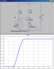
") i said it in theory i didnt try it.Its basic circuit.
i said it in theory i didnt try it.Its basic circuit.