4electros
New Member
» Home
» Analog circuits
» Digital circuits
» PIC Controller
» MP3-Player
» Tools & Downloads
» Contact
» Links
PIC
Circuits with PICs
Programmer
An A589-compatible PIC programmer
Content
» Schematic
» Paper tape board
» How it works
» Software
» In Use
» Component list
» Eagle-Layout
Language selection
PIC Programmer
Schematic and description of an A589-compatible PIC programmer
Schematic
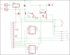
Fig. 1 - Schematic of the PIC Programmer
Template for paper tape board
Fig. 2 - Component side of the PIC programmer
Fig. 3 - Soldering side of the PIC programmer
How it works
The circuit which is presented here is based on the circuit presented in the Microchip Application Note 589 (AN589). This programmer is compatible with every software supporting AN589 programmers.
The programmer is connected to your PC with an usual parallel printer cable. I use the software PBrenner under Windows 98. Please note that in some notebooks, only cheap hardware is used, so you could get into trouble running the programmer with such hardware.
A H signal on D4 turns Q2 on, resulting in /MCLR going low (the PIC is reset). The reset condition is ended by setting D3 to H and D4 to L (Q2 is off, T1 and Q1 are on). A simultanous reset and programming mode are prevented by connecting the emitter of Q1 to D4. For correct working, it's sufficient to connect the programmer to 12 V. Data and clock signal are connected to D0 and D1. The data which is read is available on ACK. BUSY and PE are connected to ground.
The IC1 buffer is activated during programming by D2 and D5. During reading, D2 is set to L.
The resistors are needed to create the necessary logic levels.
You can use the 5 pin connector to program a PIC in its target circuit. This is called ICSP (In Circuit Serial Programming).
Software
I use PBrenner under Windows 98 by sprut.de. But every other AN589 compatible software should work as well.
In Use
Fig. 4 - PIC Programmer
Component list
1 x IC socket 40 pins
1 x IC socket 20 pins
1 x IC socket 18 pins
1 x IC SN 74 LS 244
1 x Voltage regulator 5V 7805
1 x Transistor 2N3906
2 x Transistor 2N3904
4 x Resistor 2,2 k
1 x Diode 1 N 4001
2 x Electrolyte capacitor 47 µF
Part list as PDF document (57 KB).
Looking at the photo you see that's also possible to use a standard centronics connector.
Eagle-Layout
Click here, when you want to download the foil with the layout of the board (Attention! Only ICSP version!). In order to download the Eagle-Layout-Files (schematic and routed board), please click here (79 KB).
» Top «
[Skip Prev] [Prev] [Next] [Skip Next]
[Random] [Next 5] [List Sites] [Join Ring]
» Analog circuits
» Digital circuits
» PIC Controller
» MP3-Player
» Tools & Downloads
» Contact
» Links
PIC
Circuits with PICs
Programmer
An A589-compatible PIC programmer
Content
» Schematic
» Paper tape board
» How it works
» Software
» In Use
» Component list
» Eagle-Layout
Language selection
PIC Programmer
Schematic and description of an A589-compatible PIC programmer
Schematic
Fig. 1 - Schematic of the PIC Programmer
Template for paper tape board
Fig. 2 - Component side of the PIC programmer
Fig. 3 - Soldering side of the PIC programmer
How it works
The circuit which is presented here is based on the circuit presented in the Microchip Application Note 589 (AN589). This programmer is compatible with every software supporting AN589 programmers.
The programmer is connected to your PC with an usual parallel printer cable. I use the software PBrenner under Windows 98. Please note that in some notebooks, only cheap hardware is used, so you could get into trouble running the programmer with such hardware.
A H signal on D4 turns Q2 on, resulting in /MCLR going low (the PIC is reset). The reset condition is ended by setting D3 to H and D4 to L (Q2 is off, T1 and Q1 are on). A simultanous reset and programming mode are prevented by connecting the emitter of Q1 to D4. For correct working, it's sufficient to connect the programmer to 12 V. Data and clock signal are connected to D0 and D1. The data which is read is available on ACK. BUSY and PE are connected to ground.
The IC1 buffer is activated during programming by D2 and D5. During reading, D2 is set to L.
The resistors are needed to create the necessary logic levels.
You can use the 5 pin connector to program a PIC in its target circuit. This is called ICSP (In Circuit Serial Programming).
Software
I use PBrenner under Windows 98 by sprut.de. But every other AN589 compatible software should work as well.
In Use
Fig. 4 - PIC Programmer
Component list
1 x IC socket 40 pins
1 x IC socket 20 pins
1 x IC socket 18 pins
1 x IC SN 74 LS 244
1 x Voltage regulator 5V 7805
1 x Transistor 2N3906
2 x Transistor 2N3904
4 x Resistor 2,2 k
1 x Diode 1 N 4001
2 x Electrolyte capacitor 47 µF
Part list as PDF document (57 KB).
Looking at the photo you see that's also possible to use a standard centronics connector.
Eagle-Layout
Click here, when you want to download the foil with the layout of the board (Attention! Only ICSP version!). In order to download the Eagle-Layout-Files (schematic and routed board), please click here (79 KB).
» Top «
[Skip Prev] [Prev] [Next] [Skip Next]
[Random] [Next 5] [List Sites] [Join Ring]