Hi everyone, wooo first post ")
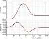
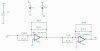
I am designing a passband filter using a high and low pass filters. When I model it using Tina8 with ideal op amps the filter works beautifully as it should.
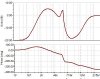
Whenever I put in real op amps I get some irregularities. It spikes at the end then the output gain is off. I have searched and searched but cannot find out why.
I believe it is possibly Harmonic Distortion but am not 100% sure.
I have attached both what I wish it to look like, what it does look like and my circuit.
If anyone could give me a hand recognising the problem I would greatly appretiate it.
Thanks you
I am designing a passband filter using a high and low pass filters. When I model it using Tina8 with ideal op amps the filter works beautifully as it should.
Whenever I put in real op amps I get some irregularities. It spikes at the end then the output gain is off. I have searched and searched but cannot find out why.
I believe it is possibly Harmonic Distortion but am not 100% sure.
I have attached both what I wish it to look like, what it does look like and my circuit.
If anyone could give me a hand recognising the problem I would greatly appretiate it.
Thanks you