Futterama
Member
Hi forum,
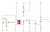
I found a CDI ignition project on RC Universe forum, and I'm having trouble understanding an oscillation part of the circuit, perhaps you can tell me how it works?
The part of the circuit marked with red should oscillate and by using L1, L2 and L3 it should generate a few hundred volts.
Can you explain how it works and perhaps tell me if there is a name for this kind of oscillation circuit (like "astabil multivibrator" is a term for a specific kind of circuit).
Look at the attached schematic.
Thanks.
Regards,
Futterama