Continue to Site

Welcome to our site!

Electro Tech is an online community (with over 170,000 members) who enjoy talking about and building electronic circuits, projects and gadgets. To participate you need to register. Registration is free. Click here to register now.

  • Welcome to our site! Electro Tech is an online community (with over 170,000 members) who enjoy talking about and building electronic circuits, projects and gadgets. To participate you need to register. Registration is free. Click here to register now.

Problem measuring AC channels drops with a Raspberry PI

Status
Not open for further replies.

Liken

New Member
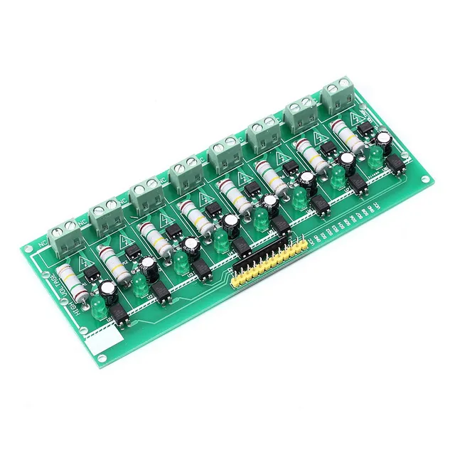
Hello. I am using this kind of AC sensing or digital input to a Raspberry Pi Board PC. There are 8 AC signals that suddenly drop in different order and times, and I try to determine the order and milliseconds between channels drops.

My problem is that my results change with different AC optocoupler boards from same manufacturer. I need at least 1ms precision and I see differences up to 50ms between boards. For example:

Channels Falling Order
BOARD A : CH1, +2ms CH2, +15ms CH3, +2ms CH4, .... (Repetitive beween tests)
BOARD B: CH2, +20ms CH3, +5ms CH4, +25ms CH1 .... (Repetitive between tests, CH1 is delayed 50 ms in Board B)

little differences in capacitors or something?

Does anybody know what kind of precision or error one can expect for AC drops with this kind of circuits? Do I need to calibrate my C program for earch board? is there any alternative?


**broken link removed**
AC-220V-MCU-TTL-Level-8-Channel-Optocoupler-Isolation-Testing-Board-Isolated-Detection-Tester-Module-PLC.jpg_640x640.jpg
 
1ms precision and I see differences up to 50ms between boards
You need to fill in the "location" in your profile. Depending on where you are the power line is 50 or 60 hz.
Your board is only looking at the positive 1/2 of the power line. It is blind to the negative 1/2. You can not have precision while being blind 1/2 the time!
There are opto isolators that have two LED inside. One for + and one for -. (remove D1) This will help greatly. (don't remove D1 until you get a different type of opto)
Next C1 greatly slows down the transistor. Because you are only looking at 1/2 the power line the transistor must be so slow that it takes many cycles to respond.

Right now; if the power line is switched off on the positive half of the cycle you have some chance of measuring it. If it is switched on or off on the negative half you can not see it until the next positive half cycle. "50mS" I believe that!
If we used the right opto, AND sped up the transistor, you will find that the power line is at zero volts twice in one cycle. The power line is at +220V and -220V for a short time it is at zero. So the transistor must have enough delay to hide "zero corssing". I think we can speed up the response to a couple of mS but not 1mS. You are measuring some thing with 50hz and you want to measure at 1000hz speed.

Next; all boards should have the same delay. I wish I had a fast and a slow board here. I think that problem is easy. Are the value of C1 the same on all boards?
 
Next; all boards should have the same delay. I wish I had a fast and a slow board here. I think that problem is easy. Are the value of C1 the same on all boards?

That's the question. I don't care delays, provided they are the same for the 8 AC channels. All the AC signals have the same phase. I am only interested about relative drop times between them. In theory capacitors and every component is the same for each channel and each board. But maybe manufacturer's tolerances for capacitors (or resistors, or optocouplers, ...) does not allow high precision to determine the channels falling order for fast drops.

The purpose of this invention is to diagnose failures in a machine. Different failures cause different falling order for AC probes in its electrical systems. You need to go to 1ms or 3ms precision to see the AC probes falling order. Otherwise it appears they fall simultaneously. With this 8 channel AC optocoupler board I can see the order (or a order), and my prototype was working and diagnosing, analysing falling patterns , but now I discover other boards from same manufacturer have differences in order, so my options are:

1) To calibrate experimentally each board, give them different delay parameters for each channel, and include this calibration in the C program increasing its complexity.
2) To look for another kind of AC optocoupler boards, with higher precision or smaller differences between units.

But my question, or curiosity, was about the expected precision for these kind of AC optocouplers in order to discriminate falling order. I mean, if they were 5V DC signals it would be easier, you can distinguish them in order of microseconds, because there are not capacitors or optocouplers involved, but for AC signals, maybe 1ms precision is optimistic, because of little differences between in theory same capacitors or optocouplers.
 
But my question, or curiosity, was about the expected precision for these kind of AC optocouplers
The capacitors are probably +/-5%. (could be 10%)
The resistors are probably +/-5%.
What is the part number on the optocouplers? I think they are not getting enough current.

With your circuit not looking at the power line 60% of the time I can't see how your can get any precision.
----edited----
Variations in the current gain of T1 will cause a 2:1 variation in response time.
 
Last edited:
What is the part number on the optocouplers?

Optocoupler is TIL111 100-300%@10mA.

With your circuit not looking at the power line 60% of the time I can't see how your can get any precision.
Variations in the current gain of T1 will cause a 2:1 variation in response time.

I know it is half wave, but AC signals are usually ON, same phase, and then, suddenly , fall down, so, I suppose every channel is at same state before the downfall, capacitors same charge, transistors same quantum state ;-), etc. If downfall is in hidden half wave, capacitors discharge at the same time and so on.
 
Not sure what your trying to prove here, but the AC goes to zero once each cycle. You can't obviosly be looking for zero. Do you want a zero-crossing detector?

Don;t forget interrupt latency. https://www.tablix.org/~avian/blog/archives/2016/04/measuring_interrupt_response_times/
What happens when all the interrupts occur at the same time? Guess 70 uS latency? 10 interrupts. Each one gets delayed 70 uS because they occur nearly simultaneously. Part values are sloppy in the design. Reactive vs. resistive powering of the LED would be more common.

There's way to much slop in the parameters. Mainly Hfe.

What about stuff that communicates at the zero crossings of the power line? e.g. X-10 https://www.authinx.com/manuals/activehome/xtdcode.pdf

So, I don;t know if you would be better, synthesizing 60 Hz with a PLL and look at the subtraction?
 
I can see this schematic is not what is on your board.
**broken link removed**
This has lead us astray. The board has a LED. The capacitor does not look like a 0.1uf.
Please double check.
---edited---
Where did you get the board. It looks like BangGood. The boards I get from then have no schematic.
 
Not sure what your trying to prove here, but the AC goes to zero once each cycle. You can't obviosly be looking for zero. Do you want a zero-crossing detector?

Don;t forget interrupt latency. https://www.tablix.org/~avian/blog/archives/2016/04/measuring_interrupt_response_times/
What happens when all the interrupts occur at the same time? Guess 70 uS latency? 10 interrupts. Each one gets delayed 70 uS because they occur nearly simultaneously. Part values are sloppy in the design. Reactive vs. resistive powering of the LED would be more common.

There's way to much slop in the parameters. Mainly Hfe.

What about stuff that communicates at the zero crossings of the power line? e.g. X-10 https://www.authinx.com/manuals/activehome/xtdcode.pdf

So, I don;t know if you would be better, synthesizing 60 Hz with a PLL and look at the subtraction?


I am studying your interesting suggestions. I think latency and interrupts are not a problem in this case, in order of uS, but I am working in order of mS.
Respecting zero crossing, pulses each 10ms, I would have to distinguish between normal zero crossing and downfall induced zeros, because I am interested in signal downfalls only. About your last point, PLL and substraction, are you referring to something like this?
KcPSx.png


Do you know about any commercial or existent boards (cheap) I could buy to test them with the Raspberry Pi?


I can see this schematic is not what is on your board.
This has lead us astray. The board has a LED. The capacitor does not look like a 0.1uf.
Please double check.
Where did you get the board. It looks like BangGood. The boards I get from then have no schematic.

Sorry. I didn't find schematic for this board so I put a similar one from this link (Thinking that conclusions would be similar):
**broken link removed**
Actual board:
0_193a3c_432b91d0_orig

**broken link removed**

On top of that, I finally see your point about precision. 50Hz is 10ms half wave. Any downfall in hidden half wave would appear as happening at the same time. So, at least 10ms error.
 
So, I don;t know if you would be better, synthesizing 60 Hz with a PLL and look at the subtraction?

I have found this on Ebay:
ac-zmpt.jpg

zmpt.png


3 Euro, AC 230V to Analog output 0-5V. Zeros 2.5V
Unfortunatelly Raspberry Pi has not analog inputs, but with and RC circuit at output maybe one could detect AC downfalls as digital input with greater precision than above AC optocoupler boards. I would like to find a existent board with a ZMP101TB plus RC as digital output as an alternative to optocoupler boards.
 
Sorry. I didn't find schematic
I don't have time to draw a schematic now.
On the input not one diode but four. So it is looking at both halfs of the cycle.
No transistor on the output.

The capacitor might be +/-20% or it might be +100/-20%. There is a chance the cap is not good for timing.
The opto could easy have a 3:1 CTR or a cheaper part might have 7:1 CTR. So there is a big chance of errors there. (the gain will be very different from one part to another)
 
Here's **broken link removed** another circuit.

So, unless your constantly digitizing the power line, your not going to see the dips. You would need to ignore things around the zero crossings as well.

I've never used a PLL before, but it's probably more frequency than amplitude, but it's still an interesting idea.

I don;t know how power line disturbance monitors work, but even so, the time your looking at is way to small to be called a sag. See https://aip.scitation.org/doi/pdf/10.1063/1.4998388 for something anyway.

Here https://dranetz.com/wp-content/uploads/2014/02/sags-and-swells.pdf is a whole paper devoted to sags and swells.

Maybe what you need to do is rent a power line disturbance monitor?
 
This is probably what you have.
upload_2018-6-3_18-49-49.png

I think this is a bad design if you want repeatability. (one board to another)
The green trace is the output. The red trace is LED current.
CTR, (Current Transfer Ratio) is LED current to transistor current in the isolator. Each part is very different.
Variations in Capacitors and variations in CTR will effect the delay.
upload_2018-6-3_18-51-45.png
 
I would use a stepdown transformer and bias the secondary to mid-voltage so that you can feed the AC voltage into a regular unipolar ADC and then continuously sample it to check if the voltage reaches 0V and stays at 0V for an excessively long time.

If you can't find a suitable transformer that can step down the voltage that far, you could include a resistive divider on the primary side of the transformer to do most of the step-down. Or instead of a resistive divider you can just clamp the voltage with diodes so you get a bipolar square wave which you then mid-bias the voltage on the other side of the transformer (so you can feed it to a typical unipolar ADC).

You could also combine all of this with a rectifier on the primary side prior to the resistive divider or clamp diodes and transformer which might remove the need to mid-bias it at all on the transformer's secondary.

The transformer is really just there for isolation/safety and to allow you to easily mid-bias the signal so you can easily feed it into a unipolar ADC. If you rectify the signal so you don't need to mid-bias it it.

If you don't like transformers, then you could replace the transformer in the circuit on the right with an opto. That won't work as well with the circuit on the left because the resistive divider won't keep the current or voltage through the opto LED as constant as the diode clamp will causing the opto to turn off in a larger area around zero cross than the diode clamp. For an opto you'll have to tweak the configuration diodes so they clamp differently than shown in the schematic so there is enough voltage and current to actually light the opto LED but the general idea is the same. As shown the diodes will clamp the signal to +/-0.7V which is enough for an ADC to measure, but not always enough to power the LED on an optocoupler.
 

Attachments

  • Capture.PNG
    Capture.PNG
    15.8 KB · Views: 89
Last edited:
What I hinted at. It uses one of those funky optos that can be made quaisi-linear because both phototransistors are physically close to one another and on the same die so the characteristics are nearly the same.
 
This is probably what you have.
View attachment 113245
I think this is a bad design if you want repeatability. (one board to another)
The green trace is the output. The red trace is LED current.
CTR, (Current Transfer Ratio) is LED current to transistor current in the isolator. Each part is very different.
Variations in Capacitors and variations in CTR will effect the delay.
View attachment 113246


Thank you for your detail. So, this circuit is almost a transformerless power supply up to the optocoupler.

Details about the components are:

Optocoupler: EL817 C644 .According to datasheet "C Series" CTR is 200-400%.
Capacitor: Chongx VENT 100uF 25V, not sure but probably tolerance 20%.
Bridge Rectifier: MB6M

which do you think is the most responsible for the variability? The optocoupler or the capacitor?
Could it be possible to substitute Capacitor ?
What would happen if you remove the capacitor? Would the output oscillate too much?
 
If you don't like transformers, then you could replace the transformer in the circuit on the right with an opto. That won't work as well with the circuit on the left because the resistive divider won't keep the current or voltage through the opto LED as constant as the diode clamp will causing the opto to turn off in a larger area around zero cross than the diode clamp. For an opto you'll have to tweak the configuration diodes so they clamp differently than shown in the schematic so there is enough voltage and current to actually light the opto LED but the general idea is the same. As shown the diodes will clamp the signal to +/-0.7V which is enough for an ADC to measure, but not always enough to power the LED on an optocoupler.

I cannot afford for the moment to do a custom design, but it seems to me that maybe transformers would be a new source of variability between channels.
What about Solid State Relays with AC input? One of them in each channel, Do you think they would present more repeatability than the above circuit?
 
Chongx VENT 100uF 25V
I can not find data on that capacitor. With no "+/-%" on the part it might be anything.
Take a fast board and a slow board and swap two of the capacitors. See of the fast/slow follows the cap or stays with the board. (only on one channel)
Next swap two of the isolators. See what happens.

When the power line shuts off, energy on the capacitor runs down until the isolator can not keep the transistor on. The two factors being how much energy is stored and at what point the isolator stops working.
 
I cannot afford for the moment to do a custom design, but it seems to me that maybe transformers would be a new source of variability between channels.
What about Solid State Relays with AC input? One of them in each channel, Do you think they would present more repeatability than the above circuit?
Variability won't matter since zero is zero in a transformer unless you start mucking with stuff. Plus 1ms is a LONG time in electronics so even if there was variability it should be well below that.

A SSR has more variability in its turn-on threshold. The circuit in you first post is fundamentally flawed in concept. Changing components won't fix that.

Replace your rectification diode with a second opto LED so it is opposite of the first opto's LED and put the output in parralel with the other opto in the same direction as the first opto output so you aren't blind every half cycle. That would go a long way.
 
Last edited:
Status
Not open for further replies.

Latest threads

New Articles From Microcontroller Tips

Back
Top