Continue to Site

Welcome to our site!

Electro Tech is an online community (with over 170,000 members) who enjoy talking about and building electronic circuits, projects and gadgets. To participate you need to register. Registration is free. Click here to register now.

  • Welcome to our site! Electro Tech is an online community (with over 170,000 members) who enjoy talking about and building electronic circuits, projects and gadgets. To participate you need to register. Registration is free. Click here to register now.

Problem in solar tracker!

Status
Not open for further replies.

Hellkeeper

New Member
Hello everyone!
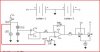
I have solar tarcker as a mid-term project, i have its schematic and all components required. I have assebled it twice very carefully according to schematic, but its not working. Since i have got this idea and schematic from a reliable source (greenwatts.info) and they also have a video of that working solar tracker, but the video quality isn't good that's why i couldn't understand it properly. Guys i want urgent help because the project submission is just after 2 days and i have to make it work.
And yeah the only one change i have made in the project is that im using two 9volts batteries instead of two 12volts batteries, so does this change not letting solar tarcker to work??

hay guys i will be really thankful to you,for any kind of suggestions!
THANKS
 

Attachments

  • schematic.doc
    31 KB · Views: 188
your cct must work even with 2x9 V, Vref you have to adjust so that at a certain point you will see your motor is stopped, when you pass that point +/- motor will run clock wise or counter clock wise. you have to expose both LDRs to the same intensity until you get 0V out by adjusting the Vref. then your CCT is ready to be installed.

cover one LDR & you will see motor running in one direction, when you cover the other it will reverse. you have to chose in the right orientation to make it to track.
 
thank you so much for the informative comment about Vref.
so do you have any guess as what would be the mistake im doing in the circuit, which is not making it work?
 
Vref... means Voltage Reference, or the reference set point of the voltage level to which the opamp changes it output state at.

Example ...This means if the opamp non inverting input (+) was set say 4 volt reference, then the inverting input (-) would need to exceed 4 volts before the output changed state (switched).
So with the (+) input held a 4 volts and the (-) input below 4 volts the output would be high ( supply voltage)
With (+) input at 4 volt and (-) input at above 4 volts the output would be low (0 volts)

It would appear you need to adjust the settings correctly for the circuit to work.
Opamps can be fiddly things to get setup correctly, but reliable ones tuned in.

Pete.

EDIT.....looking at the schematic, it is a very poor circuit with no voltage stability.
From my understanding the supply to the voltage divider pot marked ..Vref should go to the other Vref marked on the circuit, as indicated with the red line.

I fail to see why the author did not include the line in the schematic and just labeled things.
 

Attachments

  • Tracker.JPG
    Tracker.JPG
    34.4 KB · Views: 175
Last edited:
Status
Not open for further replies.

Latest threads

Back
Top