Continue to Site

Welcome to our site!

Electro Tech is an online community (with over 170,000 members) who enjoy talking about and building electronic circuits, projects and gadgets. To participate you need to register. Registration is free. Click here to register now.

  • Welcome to our site! Electro Tech is an online community (with over 170,000 members) who enjoy talking about and building electronic circuits, projects and gadgets. To participate you need to register. Registration is free. Click here to register now.

Power using little space

Status
Not open for further replies.

Boncuk

New Member
Hi all,

I stumbled over a chip made by TI, the PTN78060W stepdown switching regulator.

It offers many good properties, such as 3A output current, wide input voltage range, wide voltage output adjust, high efficiency (up to 96%), undervoltage lockout and overtemperature shutdown.

Needless to say that I ordered a free sample to experiment with it.

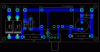
So far I have made a basic circuit for a regulated output of 2.5 to 22V. The board dimensions are really small for the power the chip supplies: 2.96X1.17inches.

Everybody is welcome to participate improving the circuit, e.g. to gain an output voltage starting at zero Volts.

Boncuk

P.S. D1 and D2 should be 1N5401 :)
 

Attachments

  • STEPDOWN-PSU.gif
    STEPDOWN-PSU.gif
    11.9 KB · Views: 169
  • STEPDOWN-PSU-BRD.gif
    STEPDOWN-PSU-BRD.gif
    18 KB · Views: 152
Last edited:
I'm surprised that they give out free samples of assembled modules.

Re your design, if the input voltage (2x 24VAC) is 50Hz (I assume this based on the 1n5401), then the 1uF filter capacitor is insufficient to provide power between cycles; I would think that 1000uF to 3000uF would be more suitable.

The output may only be adjusted from 2.5V to 12.6V, according to what I read in the datasheet.

You suggest obtaining 0V output. I'm guessing that the adjust pin is connected to the sense pin though some resistors and it might be possible to connect an opamp there (powered from the primary side) to scale the feedback voltage.

Any chance you can read the SMPS chip number? (Or even trace out part of the feedback circuit?
 
I'm surprised that they give out free samples of assembled modules.

TI is really generous concerning free samples. You can also get free evaluation kits

Re your design, if the input voltage (2x 24VAC) is 50Hz (I assume this based on the 1n5401), then the 1uF filter capacitor is insufficient to provide power between cycles; I would think that 1000uF to 3000uF would be more suitable.

The PTN78060 is a switching regulator operating at frequencies between 650KHz and 1MHz. Filtering is only required at the output. The minimum filter capacitance is mandatory at 100µF. For loads requiring more than 2A extra filter capacitors are required

The output may only be adjusted from 2.5V to 12.6V, according to what I read in the datasheet.

Sorry, I didn't look up the headlines of the tables thoroughly (2.5 to 12.6V applies to the PTN78060W and 11.85 to 22V to the PTN78060H)

You suggest obtaining 0V output. I'm guessing that the adjust pin is connected to the sense pin though some resistors and it might be possible to connect an opamp there (powered from the primary side) to scale the feedback voltage.

Any chance you can read the SMPS chip number? (Or even trace out part of the feedback circuit?

I don't have the module yet, but will try to get the internal schematic.

Boncuk
 
The PTN78060 is a switching regulator operating at frequencies between 650KHz and 1MHz. Filtering is only required at the output. The minimum filter capacitance is mandatory at 100µF. For loads requiring more than 2A extra filter capacitors are required
I was referring to the 24V AC input not being filtered to provide DC to the Dc/DC converter. The 1uF and 2.2uF that you have at the input are fine if you are feeding it DC, but not rectified AC.
 
Also, while you're fooling around with the output voltage feedback circuit (to get 0-22V), you could use another opamp (& diode OR) to provide adjustable current limiting for rectangular V-I.
 
Be aware that capacitor ESR is often more critical than the basic capacitance.

If your ESR is too high, the voltage will rise when charging and fall with discharging just due to IR drops. This is extra ripple. But exceeding the cap's ESR rating in the long term decreases its life by... get this... growing the ESR further. ESR is a huge issue in electrolytic caps and is usually the limiting factor for the lifespan.

I prefer ceramic MLCC caps whenever possible. They're crazy low ESR and the ESR is stable, and basically last forever. It's hard to get a lot of uF capacitance with them though.

Sometimes you put a low ESR ceramic in parallel with a high capacitance electrolytic. However, that primarily works for snubbing high freq, high current switching noise. Cause basically the ceramic can only offload an amount of ripple proportional to its capacitance and the rest of the ripple current is going through the larger cap anyways and any ripple going through the large capacitor faces the same ESR problems.
 
Be aware that capacitor ESR is often more critical than the basic capacitance.

If your ESR is too high, the voltage will rise when charging and fall with discharging just due to IR drops. This is extra ripple. But exceeding the cap's ESR rating in the long term decreases its life by... get this... growing the ESR further. ESR is a huge issue in electrolytic caps and is usually the limiting factor for the lifespan.

I didn't mention that C1, C2 and C4 must be ceramic caps as strongly recommended by the manufacturer of the module.

The datasheet also contains a list of recommendations for the caps including the names of their manufacturers as well as the type of ferrite beads.

Boncuk
 
Last edited:
Status
Not open for further replies.

Latest threads

New Articles From Microcontroller Tips

Back
Top