Continue to Site

Welcome to our site!

Electro Tech is an online community (with over 170,000 members) who enjoy talking about and building electronic circuits, projects and gadgets. To participate you need to register. Registration is free. Click here to register now.

  • Welcome to our site! Electro Tech is an online community (with over 170,000 members) who enjoy talking about and building electronic circuits, projects and gadgets. To participate you need to register. Registration is free. Click here to register now.

Power Supply, regulator overheating.

Status
Not open for further replies.

Hank102938

New Member
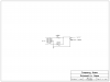
I have finished putting together a variable power supply using this design **broken link removed**
I found the initial design here. On that web page it says that this design has capabilities of up to 30V at 1.5A. But now that I have it built I realized that it's nearly impossible, at any voltage at 0.5A, dissipate enough heat with any heat sync.

I'm not quite sure what the person who wrote the original article (at the link above) was smoking, but they insist to "Be sure to put a cooling rib on IC1, at it's max 1.5 A current it quickly becomes very hot..." and a simple "cooling rib" will defiantly not solve the problem of the regulator becoming hot.

So, I want an output of 30v at at least 1A. Is there any modifications I can make (like get a different regulator) or will I just have to limit the output current?
 
As you noted, the regulator can dissipate a large amount of power, depending upon the output voltage and current. It's proportional to the output current and voltage drop across the regulator, thus it is maximum with the output is near 0V, where it would be over 30W at 1A. That's true for any linear regulator, independent of design. Only a switching type regulator will reduce this dissipation.

You need to mount the LM317 on a large heat sink using thermal grease, probably about a 4' or 5" square aluminum sink with fins if you want to output high currents at low voltages. You could also add a small fan to help cool the heat sink.
 
You have several problems. First I think the transformer is the one from radio shack (25.2 volts @ 2 amps) but a great price.
Not absolutly certain but I think this gives you 35.5 volts peak at nominal line. With your filter cap ( only 1000 ufd. and a couple of diode drops in the bridge you only have about 20 volts of real dc to try to regulate with. Give 3 volts to the regulator and you could do a nice 15 volt supply. I think you will find transformers the big ticket item to get to 30 volts so the other altenitive is to change the bridge diodes to schottky to lower the voltage drop and make the filter cap about 15000 ufd. At this point it might be cheaper to get a low drop out regulator to save some money on the caps. Now to the power problem. The problem is not when the supply is running at 30 volts but rather when it is running at the lower voltages and all the excess voltage is dropped across the regulator. At 5 volts about 30 volts will be dropped across the regulator and at 2 amps that's 60 watts. Won't work. A reasonable heat sink may be about 6C/watt (<$1) so you can kind of go from there. Let's say 12 watts -- that would be .4 amps at 5 volts at 100C case.
Think about what you really want from the supply. Do you really need 30 volts? Or would 15 or 12 be enough. Then let's go from there.
 
Most of the time I would probably only need it variable up to 12v output, to eliminate the need for batteries for testing. I'm not sure what the max amperage I would ever need from this supply is though. I'm always messing with a variety of devices that require different voltages/amperes. So take a car cigarette outlet for example, what amperage can be drawn from them? The answer to that would be the max amperage I would ever be working with I guess...

So with those values, max output of 12v at said amperage, what would I need to do to this circuit to make it work for me?
 
Another idea is to use a tapped transformer. At any given output voltage setting, say 12V, the transformer/rectifier/filter-capacitor only needs to feed enough voltage (~14V) to the regulator to keep it from dropping out, typically about 2V more than the output voltage. I used a small Variac to control the primary of the power transformer in a high-current linear power supply I still use. I built a "drop-out detector" into it, where a LED lights only if there is sufficient headroom to prevent the regulator from dropping out. I simply adjust the Variac until the Led just comes on, at which point the dissipation in the regulator is as low as possible at that given output voltage...

If you can find a transformer with multiple windings/taps, you can implement this idea with a multi-pole switch.

I even have a PIC-controlled power supply which does the tap-switching automatically.
 
Last edited:
With a CT secondary winding, if you use a full-wave bridge rectifier, you will have a choice of two output voltages. If the primary has taps (ie. 120V/240V or 100/120/140V), you can switch those, too.

If you can find one of these Stancor transformers, you have lots of choices....
 

Attachments

  • PStancorRt-201a.pdf
    252.2 KB · Views: 211
  • StancorRT-201b.pdf
    188.2 KB · Views: 194
Last edited:
Oh, I see. Well I don't think I'll be buying any more parts for this lost cause of a project. A) This project may be a little too far over my head. and B) it helps to have good and working circuit diagrams unlike the one I followed off that web site :mad:. So, goodbye $40 of over priced radio shack parts, hopefully I can find a use for them in the future.

Thanks for the help anyway...
 
Last edited:
Just think of all you have learned, one of which is, not every circuit published on a web site is worth building...:D

Another thing I have noticed, the prettier the pictures on the web site, the crappier the design is...
 
Last edited:
Regulator

Lighter outlets are usually 10 amps or so but most electronic that plug in don't take that much. The regulator is only good for 1.5 amps minimum, so if you need more you need a different design. But given the parts you have try these mods in the schematic. I'm guessing you have the Radio Shack 25.2 volt CT transformer. Get a heatsink that is good for 6C per watt or lower. Avid 7023B-MTG from Mouser might be good.
Change R2 to 560 ohms.
With this you will probably get 2 amps at 12 volts (transformer rating) and about 1 amp at 5 volts (regulator temperature). It will be hotter than a pistol but they are thermally protected.
Bet it satisfies most of your needs.
 

Attachments

  • reg.PNG
    reg.PNG
    59.1 KB · Views: 199
I have built similar power supply with LM338K IC https://www.electro-tech-online.com...-run-from-same-power-source.96845/#post782868
It is 5Amp regulator instead of your LM317 being 1.5Amp so the PSU does not overheat but it gets hot.
The heat sink is convection cooled and also by small fan inside the case, I was moving my stuff to a case that has no forced cooling and chose to use this PSU instead RS-50-12 **broken link removed** a 3 Year warranty, and being made in Taiwan is enough to consider it a deal :) Loaded at 35W the PSU is just a bit warm.
 
Last edited:
Status
Not open for further replies.

Latest threads

New Articles From Microcontroller Tips

Back
Top