Continue to Site

Welcome to our site!

Electro Tech is an online community (with over 170,000 members) who enjoy talking about and building electronic circuits, projects and gadgets. To participate you need to register. Registration is free. Click here to register now.

  • Welcome to our site! Electro Tech is an online community (with over 170,000 members) who enjoy talking about and building electronic circuits, projects and gadgets. To participate you need to register. Registration is free. Click here to register now.

Power supply question

Status
Not open for further replies.

TsAmE

New Member
Refering to the attachment and the red circle, I dont understand this statement: The current limit can be set from 0.7/(kr) to ∞ (0 < k < 1). How does the addition of the resistor across r create a variable resistor of r? Also how would you calculate k?
 

Attachments

  • Zener.png
    Zener.png
    248 KB · Views: 305
Last edited:
I understand how voltage dividers work, but in this case this whole layout confused me.

I have a question relating to this problem, this might give me clarity on the problem:

The limiting current is adjustable from 1A to ∞ by using a potentiometer (in the diagram above in the red circle). At what value will the current be limited if the potentiometer is set to the midpoint of the resistive track?

Now what I understand by this is that if the slider is on the right edge of the potentiometer, then an infinite current will flow through the base of Q (some of the current will spilt and go through r). But if the slider is on the left edge of the potentiometer, then as stated 1A will flow, since there is some resistance on the same line of the base of Q right?
 
Now what I understand by this is that if the slider is on the right edge of the potentiometer, then an infinite current will flow through the base of Q
No, If the slider is on the right edge of the potentiometer the base of a bjt is connect via pot to the right side of a "r" resistor.
So to active current limiter the load current must be greater then I_load = Vbe/r = 0.6V/r.

But if the slider is on the left edge of the potentiometer
Then base of a BJT is short via pot to the emitter (left side of a "r" resistor), So BJT is cut-off, and circuit behaves as voltage regulator without current limiter.

**broken link removed**
 
Hello there,


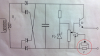
If the resistance of r in the diagram is set to 1 ohm and the pot is a higher value pot like 100ohms then when the pot is adjusted to the far right side you'll get about 600ma current limit (approximately).

There are a couple problems with this circuit as it is however. One is that they pot selection has a huge bearing on the adjustment of the circuit current limit. Even with a 10 ohm pot the resistance varies very strangely and so the adjustment isnt that good. For a few adjustments here's what we get:
r=1
Rp=10, I=0.66
Rp=5, I=0.72
Rp=1, I=1.2
Rp=0.5, I=1.8
Rp=0.25, I=3

Here's what we get using a 1 ohm pot:
r=1
Rp=1, I=1.2
Rp=0.5, I=1.8
Rp=0.25, I=3
Rp=0.125, I=5.4


The other problem is that if there is a high current surge on the output the transistor be junction can blow out, so a 100 ohm resistor is connected in series with the base of the transistor (the transistor that connects to the pot right now).

Another idea that works is to use a 1 ohm resistor for 'r', and wire the pot in parallel but connect the arm to the base of the transistor. That gives you a decent adjustment range even with a 1k pot, but you have to be watchful of the power dissipation in the 1 ohm resistor.
 
Last edited:
Status
Not open for further replies.

Latest threads

New Articles From Microcontroller Tips

Back
Top