Continue to Site

Welcome to our site!

Electro Tech is an online community (with over 170,000 members) who enjoy talking about and building electronic circuits, projects and gadgets. To participate you need to register. Registration is free. Click here to register now.

  • Welcome to our site! Electro Tech is an online community (with over 170,000 members) who enjoy talking about and building electronic circuits, projects and gadgets. To participate you need to register. Registration is free. Click here to register now.

Power wheel chair

Status
Not open for further replies.

akhil ajayan

New Member
We are doing a project about automatic wheelchair.we need the circuit to operate two 24v,250w dc bruslhess motors (max ampere 14A) control using a joystick.when joystick moving forward the wheel chair has to move forward,when it moves back wheel chair goes back,and need to operate one motor at a time for the sideways movement (we use castor wheels on front side it can rotate 360 degree).currently we have an aurdino uno, joystick,12v motor controller.basically iam a mechanical engineering student I don't know much more about ectronic circuits,please somebody help us
 
Mount the joystick rotated 45' from what you would expect the normal position to be.
Then use the two outputs to feed the two (reversible) motor controllers.

When you push forward, both outputs / motors are equally pushed positive (if you get the orientation right).
Pushing 45' either side of forward gives full speed on one motor with the other stopped.

Back & to the sides does the same with reverse.

Moving side to side from centre rotates in place, one forward and one back.

It eliminates all complex "axis mixing" circuits, as would be needed with the joystick mounted so a single axis was forward.


Edit
To clarify, with that setup you use a two axis analog (voltage output for each axis) joystick.
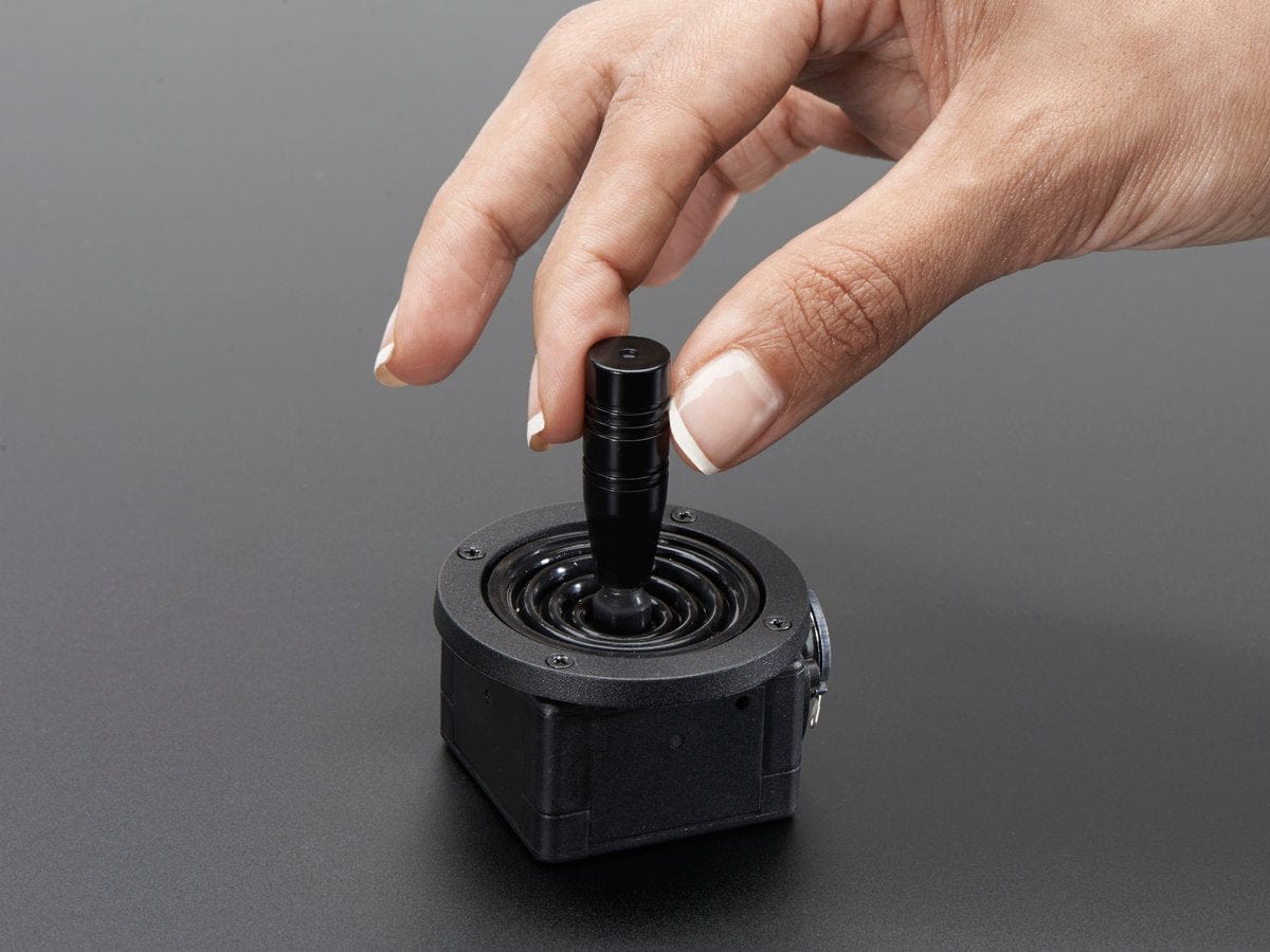
This is the type of thing likely to be used in a commercial electric wheelchair, one with an extremely long life:
That would need + & - 2.5V supplies to get the neutral output at 0V, or add a couple of opamps to add in an offset and provide some gain if needed.

To both save money and simplify the electronics, you can use one that just has two conventional potentiometers - feed the ends of the pots from the speed controller reference voltages (+/- 5V or +/- 10V, or whatever they have) and the wipers go to the speed setpoint inputs.
eg. something such as this:

Adjust the pot positions so the joystick neutral position gives 0V out.
 
Last edited:
Status
Not open for further replies.

Latest threads

New Articles From Microcontroller Tips

Back
Top