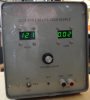
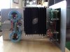
Hi everyone. I'm trying to build myself a lab power supply - up til now I have been using a computer power supply with LM338 voltage regulator, and it has been fine for my purposes. What I'd like now though is:
- greater voltage range, 3V to say 35 or 40 volts
- output current 2A or more (preferably more)
- positive / negative outputs, with a "ground" between the two (would like to be able to change the ratio between teh ground the positive/negative outputs)
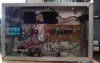
I've been looking at a bunch of IC's that do this kind of thing, but am getting quite confused by it all My current plan is to keep the ATX power supply (it produces 24V max, with 7A maximum current - forget where i read that, correct me if i'm wrong) and use a DC converter to either step the voltage up or down depending on what is required (90% of the time i'll be using a voltage under 12V).
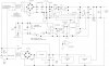
Is something like the **broken link removed** on the right track? Page 6 of the **broken link removed** has a sample circuit of an adjustable lab voltage regulator which i like the look of. I was thinking maybe combining the two, ie. using the LM5118 to produce a large voltage, and using the LM137/LM337 combination to create the positive / negative / ground outputs.
Any thoughts? Sorry, this is all unchartered territory for me")
- greater voltage range, 3V to say 35 or 40 volts
- output current 2A or more (preferably more)
- positive / negative outputs, with a "ground" between the two (would like to be able to change the ratio between teh ground the positive/negative outputs)
I've been looking at a bunch of IC's that do this kind of thing, but am getting quite confused by it all
My current plan is to keep the ATX power supply (it produces 24V max, with 7A maximum current - forget where i read that, correct me if i'm wrong) and use a DC converter to either step the voltage up or down depending on what is required (90% of the time i'll be using a voltage under 12V).Is something like the **broken link removed** on the right track? Page 6 of the **broken link removed** has a sample circuit of an adjustable lab voltage regulator which i like the look of. I was thinking maybe combining the two, ie. using the LM5118 to produce a large voltage, and using the LM137/LM337 combination to create the positive / negative / ground outputs.
Any thoughts? Sorry, this is all unchartered territory for me