Continue to Site

Welcome to our site!

Electro Tech is an online community (with over 170,000 members) who enjoy talking about and building electronic circuits, projects and gadgets. To participate you need to register. Registration is free. Click here to register now.

  • Welcome to our site! Electro Tech is an online community (with over 170,000 members) who enjoy talking about and building electronic circuits, projects and gadgets. To participate you need to register. Registration is free. Click here to register now.

Power Supply for Tube Preamp

Status
Not open for further replies.
Back in the TUBE DAYS, Full Wave Bridges were Not Common.
Solid State Rectifiers Did Not Exist.
Most Rectifiers were "Tubes" or "Selenium" Rectifiers.
And these rectifier have a Somewhat HIGH Internal Resistance to the Flow of Current.

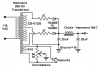
When you Rectify AC, The DC Output Voltage is 1.414 Times the input RMS Voltage.
The DC Output Current is 0.707 of the input AC Current.

Solid State Rectifier DO NOT have this High resistance to this flow of Current.
So When using the Circuit Above with Solid State Rectifiers You should put a Low Value Resistor in Series with each of these two Diodes, (Like between 10 t0 47 Ohms should be OK) to Reduce INRUSH Current that charges the Filter Cap.

You Don't say Where you Live?
But if you want to Talk, Possibly I could Phone you and explain this in Greater Detail.
(I have Free calling to Many countries)

Hope This Helps you!

Gary
 
The full wave bridge, when used with a center tap, allows +- voltages. e.g. 70 VAC CT will yield about a +-50 V supply.

If you follow the electrons around, you'll see how the + and - of the cycle works.

I ALWAYS have a hard time finding this: https://www.google.com/url?sa=t&rct...=fv6igPoQRpXn3_93H24H5A&bvm=bv.67720277,d.cWc

Note the equations for the secondary DC currents from a given AC current rating which are often neglected.
 
Wow, of course he posted the circuit, but the picture wasn't displayed when I posted that response. If I didn't look like a total dunce, I sure do now. Thanks for the help, folks.
 
Gary (Chemelec) helped me draw this up. I still need to figure out a suitable choke, I made a barely-educated guess on the Hammond 194C. Is it overkill? And what ratings do I need on the 47 ohm resistors (2-Watt?) and the hum balancing potentiometer?
 

Attachments

  • Power Supply.png
    Power Supply.png
    7.9 KB · Views: 154
You Might be OK just using a Resistor instead of a Choke.
But a Choke will do better at lowering AC Ripple.

Yes the 194C should be OK at the 50 ma Rating.
And 2 watt resistors should also be Ok.
Even 1 watt will probably do.
 
You might check out some of these.
They are Smaller.
Such as these 50 mA ones: 153H, 154H or 155H.
(Even a 20 mA Choke will probably work oK in your circuit.)

http://www.hammondmfg.com/153.htm

Unfortunately these types of chokes are not used much anymore and may not be available, because most stuff today is Low Voltage, Solid State electronics.
 
I prototyped the power supply today (finally) and it works! I'm reading 350VDC even using the 125VAC primary. We saw 380VDC with the 115AC primary. Is 350V for the B+ supply too far outside the tolerances of this circuit? If so, what's the proper way to reduce voltage in this kind of application?
 

Attachments

  • photo 1.JPG
    photo 1.JPG
    2.5 MB · Views: 154
For one, you need to put a load on the supply. The load will drop across the two 47 ohm resistors. At 20 mA, you won't drop much.

One way is to add a series resistor, another is the regulator I suggested and yet a third way is to use another transformer in series with the primary to drop the secondary voltage or two transformers to drop the secondary voltage because of the center tap. You could use a Bifilar wound torroid transformer though. e.g 2x18 V secondaries.

You basically have to phase them properly. A series connected transformer will either add or subtract. So, it's basically connect both primaries in parallel. Connect the secondaries in series. Measure the combined AC voltage. If too high, reverse either the primary or secondary. Then connect back to your circuit. Probably a little tough to visualize, but you end up applying a smaller voltage to the primary of the existing transformer. This really won;t work because of the 6.3 V winding. To reduce the secondary, you need two transformers. So, it's an OOPs.
 
If so, what's the proper way to reduce voltage in this kind of application?

If you disconnect the capacitor which connects to the junction of the diodes and the choke, you will get a much lower output voltage.

JimB
 
VoltageReadings.jpg
I prototyped the power supply today (finally) and it works! I'm reading 350VDC even using the 125VAC primary. We saw 380VDC with the 115AC primary. Is 350V for the B+ supply too far outside the tolerances of this circuit? If so, what's the proper way to reduce voltage in this kind of application?

No that Voltage Should NOT be a Problem.
Notice what is says on the Origional Tube Schematic.
+/- 20%
 
Last edited:
At 20K/ohms per volt, the input Z would be about 7M (20K*350) for those early 20Kohms/volt meters. This approaches the 10 M on normal meters. There is certain instrumentations, such as the tube tester TV-7 series where the calibration would be very wrong if you used a modern 10 M ohm input Z meter.
 
Status
Not open for further replies.

Latest threads

New Articles From Microcontroller Tips

Back
Top