Continue to Site

Welcome to our site!

Electro Tech is an online community (with over 170,000 members) who enjoy talking about and building electronic circuits, projects and gadgets. To participate you need to register. Registration is free. Click here to register now.

  • Welcome to our site! Electro Tech is an online community (with over 170,000 members) who enjoy talking about and building electronic circuits, projects and gadgets. To participate you need to register. Registration is free. Click here to register now.

Power supply filtering (for shoe box thread)

Status
Not open for further replies.
I have decided to take the advice of Mikebits and split up my Shoe box radio thread into several smaller threads. This particular thread is for the power supply of the radio.

I have most of the power supply finished (the pictures of what it looks like can be found here). There are just a few pesky issues that I'm currently resolving (heating issues, LED indicators, ect).

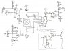
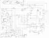
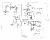
For the circuit that cools the power supply I am using 2 op-amps to control the fan. Then I added a 3rd op-amp to drive a relay to power the fan if the temp starts to become dangerous. I figured that I'd just use a quad op-amp instead of 2 or 3 separate ones. But what to do with the last op-amp?...

I decided to make a filter for the positive supply of the radio and FM transmitter to eliminate any possible ripple that may get through. There are a few questions that I have concerning this subject so that I don't need to ask in the future.

First; I have 2 different quad op-amps that I could use, the LM324 or the LM2902. Both seem to have identical slew rates, so my question is: Is the slew rate important in the design of the filter? If so how should the slew rate relate to the frequency of the input?

Second; Should I have the output of the op-amp drive a transistor or MOSFET to allow a higher supply current to the radio/FM TX? (can I even do it at all?)

Finally; Can a filter be used even if there is no noise on the line? I only ask because I did a pretty good job of filtering the noise from the line. From what I've seen the filters are just oscillators.
 
Why not use a voltage regulator IC (if you need one) instead of making one with an opamp?
 
Thank you for the replys, even if they weren't what I expected.

I already have several voltage regulators in place, I was just a fraid of some of the 120 Hz noise getting through to the radio (it would also give me something to do with the last op-amp). If you don't think that I need it then I won't add it.

The reason that I have a fan installed is because some of the parts are heating up to 100 degrees or more (Farrenhight). The space is limited inside of the box so the fan is needed so that a large heat sink is not. And the fan is also just a way to show off to the people that don't know about electronics.

But the fan has caused some problems for me. The 3rd op-amp is configured as a comparitor and it triggers a relay (to over come the voltage drop of the other op-amps and transistors that control the fan). The op-amp trips at 140 F to cool the transistor that makes the most heat (Q2). I can't get it to stay on untill it colls to 120 F before shutting off (the thermistor is on the opposite side of the heat sink that the fan is cooling). Any suggestions on how I could get the op-amp to do what I want?
 
Now it seems that I need the filter, I had the radio pluged into the new power supply last night for the first time. The radio cusmed a lot of current from the supply, however it still worked properly. Untill I tried to attach the iPod to charge, then I started to get a hum comming from the amp. When the iPod was removed then the hum went away.

Yes, I can post a schematic of my circuit, but you may need to wait a few hours untill I finish it. (the scematic is too big to post it all at once so I have to make it into sections)
 
It seems like you're making something great. What kind of radio it is? AM/FM?

There are some super quality radios that works great in battery supplies and has a Line Out.
 
The reason that I have a fan installed is because some of the parts are heating up to 100 degrees or more (Farrenhight). The space is limited inside of the box so the fan is needed so that a large heat sink is not. And the fan is also just a way to show off to the people that don't know about electronics.

Why would a radio have parts at 100 degrees?, what output power does it provide?.
 
The radio is FM, AM and also an amplifier.

The radio parts themselvs are not getting hot, it's the parts that are in the new power supply that I'm building. The transistor that is responsible for charging the battery is getting hot, but that is to be expected because the transistor has a lot of current flowing through it.

I can't seem to figure out why the iPod charger would cause the amp to hum... The only thing that they have in common is the input from the battery, but when I was testing, the battery was not being used.

I also thing that I solved the problem of the "dead zone" in the op-amp. Please tell me if I did this correcly, but I added a 100k resistor between the inverting and the non-inverting input.
 
How can you talk about a power supply that gets hot and an opamp with a "dead zone" without showing your schematic??
We don't know what you are talking about.

Your power supply gets too hot because its input voltage is far too high. The heat is not caused by only current, it is caused by current times the voltage difference of the input voltage and the output voltage. Since your input voltage is too high then the power supply gets very hot trying to throw away un-needed power by making heat. The fans use additional current which makes the power supply hotter.
 
And the fan is also just a way to show off to the people that don't know about electronics.
:D

Your radio board looks like a SANYO made..please tell me which IC it uses on the radio section, is it something like an LA1806/1826?

The speaker looks like a 20W type so as the board amplifier is.

You mean you're going to connect iPod to the transmitter fitted inside this same shoe box and receive it using the same RX? Did you try making the transmitter?

Better idea will be to get a good small AM/FM tuner and use a high power amplifier with power supply to fit inside a container and all scaring things(analog VU meter,fan etc). Use separate high quality speaker system.

Build a BA1404 fm stereo transmitter to connect to iPod and receive it thru the system.
 
The radio is FM, AM and also an amplifier.

The radio parts themselvs are not getting hot, it's the parts that are in the new power supply that I'm building. The transistor that is responsible for charging the battery is getting hot, but that is to be expected because the transistor has a lot of current flowing through it.

If parts are getting hot, them it sounds like you've made a serious design error - as AG says, show us the schematic.
 
Build a BA1404 fm stereo transmitter to connect to iPod and receive it thru the system.
The old BA1404 FM transmitter IC had terrible performance (its radio frequency drifted all over the place and it had hiss and severe distortion) so it was replaced about 10 years ago by a range of modern ICs (BH141x) that use a quartz crystal frequency synthesizer with a phase-locked-loop. They also use audio limiters and better filtering. Some kits are still sold with the old BA1404 IC.
 
Last edited:
For audioguru's satisfaction, I have provided the schematics of the circuit. Image 1 is of the power supply as a whole (the fan is not included). The second image is of just the fan control circuit (I also sketched the notch filter into the corner, just ignore that). The third pic is of the general concept of the power supply. (This is the circuit that I would like help with, it has the evil hum when the iPod is trying to charge and play at the same time but not if only one is trying to be done)

Just to answer your questions about the PNP transistor (Q2 which is getting hot) the voltage is 18V and the current is roughly 500mA, so it's dissipating 9W. That's well within the wattage rating of the MJE2955T. A larger heat sink will be added in the final circuit.

For Transistor; yes, the radio was made by Sanyo. I looked up the data sheet for the LA4108 and I got absolutely no help in how to rebuild the circuit, so I chose just to leave the amplifier and the radio receiver alone (they would most likely not work if I tried to rebuild the circuit). No, the upgrade of the radio will have an FM transmitter built into it so it can broad cast to a more power full radio [sinister laughing]. The radio already has an auxiliary jack built into it. But yes I intend to add a VU meter (and a lot of other things)
 
Sorry about not including the schematics in the previous post. I have uploaded them this time, but it would not upload them in the correct order (really weird).

The new order of the schematics are as follows:

1) Fan Control

2) The entire power supply (minus the fan control)

3) The part of the circuit that is causing some problems
 

Attachments

  • Shoe Box Radio (f&#.jpg
    Shoe Box Radio (f&#.jpg
    436.4 KB · Views: 196
  • Shoe Box Power su.jpg
    Shoe Box Power su.jpg
    1.2 MB · Views: 186
  • Shoe Box Power su.jpg
    Shoe Box Power su.jpg
    318.2 KB · Views: 202
The output voltage of your transformer is not labelled and the positive rectified and filtered voltage from the bridge recifier is also not labelled.
One 2N3055 transistor is short-circuiting the positive supply to the radio.
 
The transformers output voltage is 33V RMS, the voltage on the rectified end of the circuit (just calculated) is roughly 45.2V DC The 3055 is not shorting the radio, the collector is tied to the negative supply for the radio. However, I just replaced it with a 2955 on the positive supply because when the iPod was connected for charging, it was completing the circuit for the amp (I forgot the most important rule of electronics, all grounds are connected).
 
Guess what? Your transformer voltage is way too high which makes the heat.
33VAC has a peak of 46.7V which is dropped 2V by the full wave rectifiers to 44.7V.
But your Mickey Mouse discrete regulator has an output of only 17.3V so the series pass transistor dissipates (44.7V - 17.3V) x 0.5A= 13.7W because the transformer's voltage is way too high.
 
The Issue of heat with the 3055 transistor is under control, it's the heat with the 2955 responsible for charging the battery that is concerning me a little. I have a heat sink that is ready to be used on the 3055 and a much better heat sink ready for the 2955, but I would still like to have the relay activate the fan at 140*F and stay on until it drops to about 125*F.
 
Status
Not open for further replies.

Latest threads

New Articles From Microcontroller Tips

Back
Top