Continue to Site

Welcome to our site!

Electro Tech is an online community (with over 170,000 members) who enjoy talking about and building electronic circuits, projects and gadgets. To participate you need to register. Registration is free. Click here to register now.

  • Welcome to our site! Electro Tech is an online community (with over 170,000 members) who enjoy talking about and building electronic circuits, projects and gadgets. To participate you need to register. Registration is free. Click here to register now.

Power problem, noise.

Status
Not open for further replies.

harps

Member
hello there.

I have a problem with my design. I have an audio design placed together with an led system which is controlled by a micro controller. They both (USB and audio)share the same power supply which is causing problems, I believe.

The audio system sounds great by itself, that is until i connect up the micro controller and light up a few leds.Then there is a terrible interference noise and pulse sound.

I wonder, do I need two separate ground planes and to somehow use diodes to separate the audio system power from the micro controller and LED power sources?

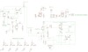
Here is a schematic to help explain the system. Thank you for any help you may offer : )
pcb-power-problemb_zps40e3bbe8.png~original
 

Attachments

  • pcb-power-problem_zps06363524.png~original
    pcb-power-problem_zps06363524.png~original
    48.3 KB · Views: 201
Last edited:
No schematic.

If the value of the main filter capacitor is high enough and the ground for the audio circuit and the ground for the LED circuit meet at the negative wire of the main filter capacitor then maybe there will be no interference.

The layout of the pcb might be allowing capacitor-coupling of pulses through the air to the audio circuit. Then a shield is needed.
Wiring. The audio input wires might be too close to LED wires.
 
Does the power supply have enough grunt to power both circuits, and does it have generous decoupling? If not, the supply will sag and that could result in the interference you get.
 
hello. there is a picture now.

it is a large picture; but by clicking on it it should zoom it in.

When the USB micro controller powers leds 'without' the transistors seen in the diagram and without power
from the regulator ( so self powered from usb) the noise goes away, it is only when I connect the power from the regulators or try to power leds
via transistors that the noise is heard through the headphones.
: ?
 
hi alec.
the external psu that feeds the regulators can provide 1.2 amp. i shall a look for another with higher capability.

"generous decoupling" I am not sure. I am still a novice.
 
Hi Alec , wow , i changed the PSU and all is well,

It must have just been on the edge of its capability to provide current?

I was so worried. I had printed pcbs. LOL. But I knew i had it working before, I thought it might have been a phantom ground loop or something?

Surprisingly, I still have some hairs left on my head after all the stress.
I shall comb them over for Christmas.

Thank you for the ideas both of you.

: )
 
It is hard to know what is happening. It looks like you have a Arduino connected to the +5V. Probably with long wires. Assuming it does not pull too much power that is fine. Then you have 5 wires back to the audio board that drive LEDs. That concerns me. I can't see you PCB layout which could be much of the problem. For a test I could cut loose the ground and +5V for the LEDs and connect them back to the Arduino. Now there will be two more wires going to the Arduino. All this is under the phrase "ground loop".
---------------------
edited: While I typed you fixed the problem. good
 
If you place a large electrolytic accross the old psu, say 2200uF it might well work fine.
Its good pratice with this kind of thing to take all the audio grounds to one point, and all the digital grounds to another point close by then connect them both to the power supply ground, with a large cap at that point, shunted by a 100nf cap.
Then you'll have less ground related issues and you can disconnect and play with the grounding to sort out any issues.
 
hello : )

I have all my grounds ( digital and audio) connecting to a single large ground plane.

I gather you suggest not to do this in future and instead use individual ground channels/routing keeping the audio and digital completely separate
around a circuit board and then only near the regulator have two points where they coonnect along with the two suggested capacitors?

So I should never to use a ground plane when mixing audio and digital on the same board?

thanks for clarification.
Yes only bring the grounds together at the large filter cap. Its called star grounding if you would like to look it up.
Also try and keep all the Audio on one side of the board and the Digital on the other side as much as possible.
 
Harps you got that perfectly, your not a complete noob then.
 
Yes only bring the grounds together at the large filter cap. Its called star grounding if you would like to look it up.
Also try and keep all the Audio on one side of the board and the Digital on the other side as much as possible.


thank you very much 4pyros. : )

+ dr pepper : )
 
Status
Not open for further replies.

Latest threads

Back
Top