Continue to Site

Welcome to our site!

Electro Tech is an online community (with over 170,000 members) who enjoy talking about and building electronic circuits, projects and gadgets. To participate you need to register. Registration is free. Click here to register now.

  • Welcome to our site! Electro Tech is an online community (with over 170,000 members) who enjoy talking about and building electronic circuits, projects and gadgets. To participate you need to register. Registration is free. Click here to register now.

Power(load) Control

Status
Not open for further replies.

Sarac

New Member
well,

With my poor english, I realy don't know how to explain my problem for designing a control circuits.

I'm trying to control variable load, powered by parallel 2 x three phase generator. What i want is when loads are drops to a preset level, one of the generator to be switch off by means of a contactor.

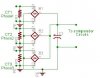
I have designed a voltage control circuits ( an under voltage cut off circuits by an op amp IC 741 supplied by current transformer connected one of a 3 phase ) it worked fine under 1 phase, but i couldn't controll any loads if sourced from any other phase rather ten the op-amp circuit is connected.

it should have sensed all the load changes regardless the phase, which the load gets power.

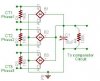
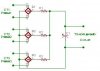
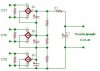
So i think, the op-amp circuit i constructed should be conected all the three phases at the same time which then will be able to sense the changes of the load current occures at either phase. ( I presume instead of only 1, i should use 3 current transformer connected at all phase )

the question is HOW IT SHOULD BE CONNECTED

P.S. syncronising of Generators in parralel is not a problem and not to be worried about it.

Hoping to clarify my question well enough.

thnks to all replies.
 
Firstly, I assume that your loads are connected in star (wye), not delta - is this correct?

Do you want to cut out a generator when ONE load drops, or when ALL loads drop?
 
Phasor said:
Firstly, I assume that your loads are connected in star (wye), not delta - is this correct?

Do you want to cut out a generator when ONE load drops, or when ALL loads drop?

hmm not realy,

the generators are supplying current to all kind of electrical appliances,
such as motors, ( three and one phase ) lights.. and there isn't only one load, there are different kind and large number of load exist and consuming power from 2 generators.

what i want is to cut out a generator when the load is little enough for
1 generator and the other is not necessary to be on.

So the total load should be monitored and cut one of the generators off when the total consume of power goes under a certain level.

hope i could explained the stiuation

regards,
 
Sarac, it should not be difficult to do. Can you answer:

1. What is the low current limit when the load can be handled by one generator (ie. when you want to switch off the 2nd generator)?
2. Is that current per each phase?
3. What is the likely maximum differences between currents for each phase?
4. Do you want the circuit to switch on the 2nd generator again when needed? If so, with what hysteresis?
 
pebe said:
Sarac, it should not be difficult to do. Can you answer:

1. What is the low current limit when the load can be handled by one generator (ie. when you want to switch off the 2nd generator)?
2. Is that current per each phase?
3. What is the likely maximum differences between currents for each phase?
4. Do you want the circuit to switch on the 2nd generator again when needed? If so, with what hysteresis?

Pepe,
thnks for your reply.

1- i don't know the low level limit of the current and i didn't think to measure it. There is an KW meter connected to the each generator and thought it would be ok if we cut the generators off whichone's meter reaches to near to zero.
2- Yes
3- Not known
4- No. if needed it will be put back on manualy.

Pepe, i didn't even think to measure current but generators are 105 KVA each. Instead of current i wanted to play with voltage which produced by a Current Transformer ( CT ).
I have connected 1 CT to one phase then i measured 5,4 Volt at max load
and 4,2 volts at min Load ( KWH needle was at near zero at 4,2 Volts )
so i thought if a voltage comparador designed and make it to cutt the generators off by means of a Contactor would do the work. i managed it with one phase but i couldn't make it work under three phase.

What i think is to put a CT to each phase and produce 3 voltage then make
it combined then after feed a voltage comparador which set a low level to cut off.

I don't know if my though is correct and can be managed somehow.

But i have come across an article lately and it says nearly what i thought.
please check it here,
https://www.e-insite.net/ednmag/archives/1995/090195/18di1.htm

and advise if it could be adopted to my project.

thnsks for yr help,
 
Hi Sarac,

The link you give shows how you can use an op-amp to obtain the third phase amplitude, when you know the other two. The current transformers (CTs) give currents which you put through resistors to get voltage amplitudes (you MUST have the resistors across the CT secondaries or you'll get some very high voltages produced).

Yes, you can use the circuit shown to save yourself a current transformer. You will then have the voltages for three phases. But these are AC and you cannot combine them directly because of the phase angle differences. They need to be rectified to get DC. You can simply use a diode/cap/resistor combination for each CT and take the voltage from across the cap. There are two ways to use this DC.

1. The first is to combine the three levels by using a resistor from each and feeding them to the inverting input of an op-amp, with a feedback resistor back from the output to control the gain. This will give the average of the three levels and would be useful if you were assessing the overall power from the generator. The non-inverting input would go to a pot with which you could set the voltage threshold required. When the input from the CTs fell below the chosen level, the op-amp output would go high. You could use that to switch a transistor to control a relay which shuts down the generator.

But there is a possible problem: The method assumes that all 3 phases carry approximately the same current. If they don't and there are single phase loads which load up one phase excessively then you could be shutting down the second generator when the power was assumed to be within the limit, yet the current in one of the phases could be exceeding what one generator could safely handle. It could have dire consequences.

2. The second method overcomes that problem by sampling each phase and using the largest voltage as the sampled data. It means that the generator will not be shut down whenever any of the phases is above limit.

For this, use a diode from each CT to charge a common capacitor. You need a discharge resistor to give a time constant of, say, 1second (10uF and 100K). From the cap, feed to an op-amp as before.


I hope that's enough information for you. If you want more detail, just come back.
 
pebe said:
Hi Sarac,

2. The second method overcomes that problem by sampling each phase and using the largest voltage as the sampled data. It means that the generator will not be shut down whenever any of the phases is above limit.

For this, use a diode from each CT to charge a common capacitor. You need a discharge resistor to give a time constant of, say, 1second (10uF and 100K). From the cap, feed to an op-amp as before.

Pepe,

As per your suggestion i drawn following diagram,

Is this what you say to be added to the Comparador Circuit?
do you think this can work?
If i understand you wrongly and if this is not what you say can you draw a schema for helping me out.

Hope i'm not bothering you or other members of this forum

thanks a lot.
 

Attachments

  • 3Phase.jpg
    3Phase.jpg
    9.7 KB · Views: 732
No, for adding three voltages, connect the bridges in serial.
 

Attachments

  • 3Phase_214.jpg
    3Phase_214.jpg
    12.8 KB · Views: 710
Hi Sarac,

Your circuit is nearly right for what I described as Method 2 (sensing the maximum current in any phase). But you don’t need R1, R2, R3. Instead, connect the +ve output pins of all the bridge rectifiers together and connect them to the +ve of C1. C1 will then charge to the highest phase. You can use the op-amp output (as in the link) for the third phase. Construct it exactly as they show.

BTW, you need load resistors on the CTs – it is most important. They are current operated devices and the secondary current is inversely proportional to the primary current times the turns ratio. In your case, assuming 220V per phase, you will have around 150A max per phase. If you have no load connected across the secondary winding then the voltage across the winding will increase to try to force current through the non-existent load, and that could become many thousands of volts! I don’t know which CTs you are using but load resistors may already be fitted. The turns ratio of the CT and the value of the load resistor will determine what voltage you get.

As I said, the voltage across C1 will be proportional to the highest current in any of the phases (don’t forget that 1.2V will be lost across the bridge rectifier). If you feed this directly to one input of an op-amp, you can feed the voltage you have selected with a pot, to the other input. The op-amp then is used as a comparator.

The circuit shown by Sebi is for the measurement of power, which I called Method 1. Sebi is using the voltages in series whereas I was summing them at the inverting input of the op-amp to get their average value. The end result would be the same.

If you can give some more details, ie. 110v or 220v, CT turns ratio, and loading resistors, I can work out values for the op-amp, if you want.

Pebe.
 
pebe said:
Hi Sarac,

Your circuit is nearly right for what I described as Method 2 (sensing the maximum current in any phase). But you don’t need R1, R2, R3. Instead, connect the +ve output pins of all the bridge rectifiers together and connect them to the +ve of C1. C1 will then charge to the highest phase. You can use the op-amp output (as in the link) for the third phase. Construct it exactly as they show.

BTW, you need load resistors on the CTs – it is most important.
Pebe.

Pepe, Sebi thnks for the reply,

I have redrawn the schema as per Pepe's correction. I assume that parrallel connection of the bridges would be more accurate then the serial connection. I have also included a ground connection ( like shown, in the link )

Regarding details Pepe ask,
1- CTs turn Ratio are 250/5 ( 1/50 ) each
2- Generators producing 380v / 220v
3- Generators are 132 KVA
4- CT Load resistor's value = not known, I'm also wondering the value of
the resistors too.

now, my questions are

1- Would the modified schema work as desired ?
2- What will be the resistors value? ( i.e. R1,R2 and R3 )
3- What will be the Cap's value?

plase advise and correct me if anything seems wrong.
Then i will construct the circuits to blow up the generators :)
( hope not )

thnks again
 

Attachments

  • 3phase1.jpg
    3phase1.jpg
    16.1 KB · Views: 756
Attention! Don't connect ground to bridge input and output, choose one, i recommend the DC-side. Resistors value 200...500ohm, capacitor should be 10...100uF, and need a parallel resistor for discharging, because the comparator input no loaded it.
 
Like Sebi said, don't ground the CT winding - you have already got the circuit grounded at the C1 -ve lead. Yes, you need a discharge resistor across the cap. As I said earlier you need a time constant of somewhere about 1second. I suggested a 10uF cap and a 100K resistor.

You have drawn 3 CTs. Are you not intending to use the circuit from your link which uses two CTs plus an op-amp? I suppose it will depend on the cost of a CT.

Your 132KVA generators produce 200A per phase at full load. With a 50:1 CT you would get 4A secondary current, which I thought was an awful lot to be handling for this application. To get about 5V from them you would need 1.5ohm resistors at 24Watts each!

I have looked up specs for URD America CTs as quoted in the circuit from your link, and CTs there handling 200A have a turns ratio of between 400:1 and 1000:1. It looks like they are all designed to have the cable pass through a torroidal transformer, so the primary is only one turn. Are CTs you have specific for your generator's current?
 
Pepe, Sebi..

Ok, i have re drawn the circuit ( as your description ) i think all is in order now.
I have well understood everything in this proposed circuit
only one thing need to be clarified is that the resistor No 4 ( R4=100K ), why do i need to discharge the 10uf Cap. for 1 sec. time constant since
the comparador circuit shuts down the generator, this circuit will be
de energised and everything to be reseted, being ready for next use.

BTW i don't want to make this project more complicate for saving a CT thus i will use 3 CT. The link i have provided was just for info.

The CT i am intending to use is regular CT which are generaly used to display current with analog Ammeter. It is supposed to get 5A, when 250A power consumed ( so it is called 250/5 CT ).
i'm using these CTs Bcs i have found only these ones.

Thank you for your great help.
 

Attachments

  • 3Phase2.jpg
    3Phase2.jpg
    17.1 KB · Views: 635
Sarac said:
Pepe, Sebi..

..... only one thing need to be clarified is that the resistor No 4 ( R4=100K ), why do i need to discharge the 10uf Cap. for 1 sec. time constant since
the comparador circuit shuts down the generator, this circuit will be
de energised and everything to be reseted, being ready for next use....
The reason for the 100K resistor is to discharge the capacitor after a short time. If you didn't, and the current dropped from 100A to 20A, the cap would hold its charge and your comparitor circuit would think that 100A was still flowing. The ideal discharge time is as quickly as possible. But if you make it too fast then the voltage on the cap will pulse high as each phase passes its peak and then fall again as the cap discharges, giving you ripple. As your circuit is looking for a drop in cap voltage to indicate the load current has decreased, it would cut out the 2nd generator before it should.

If you pick a time constant of about 1second, the cap voltage will only drop by a small amount between phase peaks, yet will quickly respond to a reduction of voltage over a couple of seconds.

I hope that has clarified the point.
 
Status
Not open for further replies.

Latest threads

New Articles From Microcontroller Tips

Back
Top