Hey.
In the last thread, i was suggested to measure the true power consumed by an SMPS in the following way.
Turning the existing SMPS:
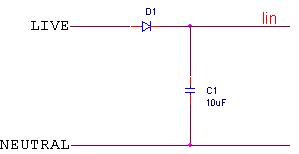
Into this:
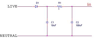
And measure the current through the sense resistor (R1) and the voltage across C1 or C2 (there shouldn't be a significant difference between their voltages).
My question is, why connecting the sense resistor between C1 & C2, and not after C2?
After all, The current through R1 (at the current configuration), is Iin + I_C2, and I dont care about I_C2, but only about Iin.
I dont care about I_C2 because C2 doesnt exist in the original SMPS, and beacuse the current through C2 creates reactive power, and i care only about true power.
I'd like to receive your opinion on it.
Thank you in advance.
In the last thread, i was suggested to measure the true power consumed by an SMPS in the following way.
Turning the existing SMPS:
Into this:
And measure the current through the sense resistor (R1) and the voltage across C1 or C2 (there shouldn't be a significant difference between their voltages).
My question is, why connecting the sense resistor between C1 & C2, and not after C2?
After all, The current through R1 (at the current configuration), is Iin + I_C2, and I dont care about I_C2, but only about Iin.
I dont care about I_C2 because C2 doesnt exist in the original SMPS, and beacuse the current through C2 creates reactive power, and i care only about true power.
I'd like to receive your opinion on it.
Thank you in advance.
Attachments
Last edited:
