Jules_Theone
Member
Hi everyone,
I haven't been on for a while, but the time has come for my final year (BSc Elec Systems) Project and I have an idea. The basic outline is as follows:
A power conditioning circuit to convert a wide range of input voltage (approx. 1.2v - 50v AC or DC) to a stable 12V DC. It won't be very high power, perhaps less than a watt per module but many can be paralleled together to produce higher currents at 12V. The modules are connected together through a 12V connection running next to the standard AC mains supply. Possible sources if energy include (micro) wind, solar, peltier cells, kinetic energy harvesters on doors or mats etc. Low voltage DC is safer, easier to connect together as only the voltage needs to be matched to be compatible and there are lots of 12V DC appliances that can be powered from this already on the market. While AC needs to have the phase, frequency and voltage matched to connect multiple sources.
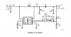
I plan to use a buck-boost topology switching power supply to step-up the input voltage to around 100v then back down to regulated 12V. I have found a circuit (attached) from a switching regulator LM5001 datasheet which looks very similar to what I want to do although I think there will need to be a rectifier on the input to convert from AC or either polarity DC.
Basically I wanted to run my ideas past some people with more experience in power supplies etc. Any suggestions or things to avoid?
Thanks in advance,
Jules
I haven't been on for a while, but the time has come for my final year (BSc Elec Systems) Project and I have an idea. The basic outline is as follows:
A power conditioning circuit to convert a wide range of input voltage (approx. 1.2v - 50v AC or DC) to a stable 12V DC. It won't be very high power, perhaps less than a watt per module but many can be paralleled together to produce higher currents at 12V. The modules are connected together through a 12V connection running next to the standard AC mains supply. Possible sources if energy include (micro) wind, solar, peltier cells, kinetic energy harvesters on doors or mats etc. Low voltage DC is safer, easier to connect together as only the voltage needs to be matched to be compatible and there are lots of 12V DC appliances that can be powered from this already on the market. While AC needs to have the phase, frequency and voltage matched to connect multiple sources.
I plan to use a buck-boost topology switching power supply to step-up the input voltage to around 100v then back down to regulated 12V. I have found a circuit (attached) from a switching regulator LM5001 datasheet which looks very similar to what I want to do although I think there will need to be a rectifier on the input to convert from AC or either polarity DC.
Basically I wanted to run my ideas past some people with more experience in power supplies etc. Any suggestions or things to avoid?
Thanks in advance,
Jules