Continue to Site

Welcome to our site!

Electro Tech is an online community (with over 170,000 members) who enjoy talking about and building electronic circuits, projects and gadgets. To participate you need to register. Registration is free. Click here to register now.

  • Welcome to our site! Electro Tech is an online community (with over 170,000 members) who enjoy talking about and building electronic circuits, projects and gadgets. To participate you need to register. Registration is free. Click here to register now.

Power circuit

Status
Not open for further replies.

Ricardoco

New Member
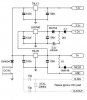
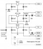
Hi all, this is the part i find hard it is constructing the hard ware for my project, i am trying to do it in a modulay fashion so that it makes it easier to understand, my project will require the usual 5v for the microcontroler, plus a 3.3 and a 12 for other devices i intend to use. Could someone have a look over this diagram and see if i have it right, or if there is a better way then please feel free to post it. :D (Ive moved this post because i posted it in Microcontrollers by mistake) Ooooops Sorry:

(I have deleted the original diagram to save space on this thread the releant one is at the end)
 
My first thought is the crystal?, why is this in the power supply?.

It needs to be as close as possible to the PIC, along with the two capacitors as well.
 
Errr you got me there nigel :lol: i must have got a bit carried away and the worst thing is i never even noticed!!. and im not sure if my project will even need one as im using an 18F that has one built in... thanks
 
The 3.3volt supply looks very odd.

Why is there an LED in series with the supply?, you will drop ~2.2volts across that thing.

100 ohm in series with the battery, what charging current does that give from the 3.3v supply?


JimB
 
Do you think so JimB.
Ahh yes I see it now! this is why i post here because people are so helpfull
thankyou for that you are so correct i have revised the diagram, Look ok now?

Revised thanks to jimB .. and Nigel

(I have deleted the original diagram to save space on this thread the releant one is at the end)
 
I mean, the lithium battery don't like the charging. Need a serial diode...
 

Attachments

  • powerblock2b_888.jpg
    powerblock2b_888.jpg
    7.1 KB · Views: 1,047
Well that is just what i thought which is why i posted. but take a look at this link and tell me what you think:
**broken link removed**
 
Ricardoco said:
Well that is just what i thought which is why i posted. but take a look at this link and tell me what you think:
**broken link removed**

I think you will have a hard time finding the LM3840 regulator.

The LM3940 on the other hand, would burn up when you fed 15V to its input as it is only rated to 7.5V max.
 
Thanks eblc1388 what would you suggest as a possible remedy to that then......
 
Ricardoco said:
Thanks eblc1388 what would you suggest as a possible remedy to that then......

Connect LM3940 input to voltage less than 7.5V, perhaps to the output of 78L05?
 
Hmmm ok eblc1388 is this better? by the way thankyou for your help.. :D
 

Attachments

  • powerblock2c.jpg
    powerblock2c.jpg
    22.8 KB · Views: 1,012
Now you have moved the 10uF away from the 1N4004 and the two(78L05 and 78L12) regulators input has no large value capacitor. You should consider adding a 10-100 uF capacitor at the input of the two regulators.

The diode type 1N4148 at the MCLR pin is not recommended. Microchip datasheet stated that it should be a Schottky type, like the BAT54.
 
Ok do you mean replace the two 100n capacitors with say 10uF one on each? (sorry if this sounds a stupid question but i want to make it clear in my head..
 
Ricardoco said:
Ok do you mean replace the two 100n capacitors with say 10uF one on each?

I would suggest you keep the two 100nF caps. You don't need to add two 10uF capacitors. One is sufficient.

Is the power source coming from an alternator/engine? If so you'll need more filtering before you can use it.

You should also try to find other choices for the LM3940 as it is a large size TO-220 type regulator rated at 1Amp. I think there are alternatives of a smaller size.

I can't give any suggestion because I have never used any 3.3V regulators before.
 
Ok found a regulator that may fit the bill and it is in a TO92. i was going to take the supply directly from the 12v boat battery and that is connected to the alternator what other smoothing whould you suggest?.
 

Attachments

  • powerblock2c_134.jpg
    powerblock2c_134.jpg
    23.2 KB · Views: 980
Ricardoco said:
Ok found a regulator that may fit the bill and it is in a TO92. i was going to take the supply directly from the 12v boat battery and that is connected to the alternator what other smoothing whould you suggest?.

Now there is another minor problem. The 78L12 can only provide you with a 12V output with at least 15V input. So if the engine is not running, you might expect to see less than 12V output if the battery voltage is only 13.6V or less. Make sure the circuit getting this voltage does not mind.

On the supply filtering issue, the aim is to remove the voltage spikes on the power lines using filters. These can be R-C or L-C types and follows by a special transience absorber called "Transorb" which is just a posh name for a zener like diode. Never used them but learn that from the forum and have absolutely no idea where in UK one can get that.

Other users of this forum who had actually fitted devices on vehicles/boats can offer you better recommendations on the filtering issues.
 
Well the 12v regulator is more to put a cap on the voltage than anything else the device that will use this line has a voltage window of 9-15v so im hoping that any drop in voltage will be well within limits. As for the zener thankyou for the clue which i will investigate.. may i take this moment to thankyou for your time eblc1388, and not forgetting the input from others who have participated in this thread thankyou all...You never know someone other than me may find this thread usefull.. :D
 
eblc1388 said:
Now there is another minor problem. The 78L12 can only provide you with a 12V output with at least 15V input. So if the engine is not running, you might expect to see less than 12V output if the battery voltage is only 13.6V or less. Make sure the circuit getting this voltage does not mind.

Note he said, 78L12, not 7812. L is a designator for an LDO. Dropout is 1.7v for a 78L12.
 
You still have the LED in series with the 1.2v output. This is probably an error.

The diode going to MCLR is rarely useful and can cause some serious problems. The resistor is still necessary.

Why the 1N4004 on DCin?

We could help you better if you could describe exactly what you need to do. What are your loads? What are you powering it with?
 
Oznog said:
Note he said, 78L12, not 7812. L is a designator for an LDO. Dropout is 1.7v for a 78L12.

"L" certainly does not mean low dropout. It stands for low output current in the 78/79 series.

The 1.7V you have quoted is only the typical value at 40mA output and from studying the datasheet graph the actual voltage differential at 100mA could be well over 2V. It can't be a low dropout regulator with such voltage differential.

From the datasheet, the worst case value of input voltage to maintain regulation is still 14.5V or more.

Oznog said:
You still have the LED in series with the 1.2v output. This is probably an error.

No, it is not. The purpose of the LED is to drop the 3.3V into 1.2V using the voltage drop across the LED. Read the link the OP had posted on the original circuit design.

Oznog said:
The diode going to MCLR is rarely useful and can cause some serious problems. The resistor is still necessary.

Not only is it useful, it is a requirement to prevent 13V from going to the other part of the circuit or the PIC itself when one do HV in circuit programming. Leaving out the diode risk damaging the rest of the circuit unless one never use HV programming and stick only to LVP.

When you said it can cause series problems, can you share what problems it can cause as adding the diode is what is stated in Microchip datasheet.
 
Status
Not open for further replies.

Latest threads

New Articles From Microcontroller Tips

Back
Top