PWKseeker_127eq
New Member
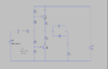
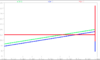
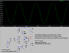
Good Day to everyone, I'm building a circuit in Ltspice particularly a power amplifier. I'm trying to generate a undistorted (straight) waveform in the simulation, however, I always get different waveforms which are always distorted or have curves.
I need help in generating a straight waveform in every voltage and current component (Ve1, Vc1, Vb1, Vb2, Ve2, Vn001) in the circuit. Can you assist me in where I got wrong in the circuit? Thanks
Ve1, Vc1, Vb1, Vb2, Ve2, Vn001, Vr8, and Vin are the ones I need to obtained an undistorted waveform. Thanks again!