Continue to Site

Welcome to our site!

Electro Tech is an online community (with over 170,000 members) who enjoy talking about and building electronic circuits, projects and gadgets. To participate you need to register. Registration is free. Click here to register now.

  • Welcome to our site! Electro Tech is an online community (with over 170,000 members) who enjoy talking about and building electronic circuits, projects and gadgets. To participate you need to register. Registration is free. Click here to register now.

Positioning a current sense resistor in a mains powered dimmer circuit

Status
Not open for further replies.

ramuna

Member
My question today concerns how to position a current sense resistor in a 240V rms 50Hz mains powered resistive load dimmer circuit, under microcontroller control.

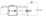
I have uploaded a schematic for such a conventional dimmer (dimmer_a), which I found on the Web (https://www.edaboard.com/threads/using-an-opto-triac-moc3020-to-control-a-mains-lamp.155997/ ) and have slightly modified.

My application is for passing 10 Watts of power through a resistive load. The load resistance starts at 1.0k and then rises over time to beyond 30.0k. So, I need to periodically measure the load resistance and adjust the triac firing angle to feed approximately 10 watts into the load.

At 5.76k and above, the power in the load will drop below 10W even with the triac continuously on. At that stage I will keep the triac continuously on. When the load resistance reaches 30k, power will be shut down and the heating cycle will be over.

I am thinking of measuring load resistance by measuring the average current through the load while passing a known rms voltage through it. I would like to use a low value current sense resistor in series with the load, rectify the voltage across it using a precision rectifier and then smooth its output with a RC integrator.

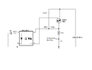
However, I cannot figure out a way to place this resistor in the conventional circuit dimmer_a. Therefore I have modified it, so that I can have a common ground between the mains part of the circuit and the 5v dc control power supply (and also a +5V to -5V dc power supply for the precision rectifier), and so I can place the current sense resistor referenced to this common ground.

This modified circuit is shown in uploaded schematic dimmer_modified.

Kindly examine the dimmer_modified schematic and check if this will work as I intend it to work. AND IF IT IS SAFE TO USE. I want to keep the Magic Smoke safely locked inside the components.

Incidentally, at load resistance values below 5.76k, I will measure the current through the load with the rms voltage through it set at 1/10th mains voltage (24V rms - @ phase angle of 159 degrees or 2.78 radians). At and above 5.76k I will use the full mains voltage.

Any better ideas to achieve the same purpose are very welcome!
 

Attachments

  • dimmer_a.gif
    dimmer_a.gif
    5.7 KB · Views: 382
  • dimmer_modified.gif
    dimmer_modified.gif
    8.6 KB · Views: 476
Last edited:
All your circuits are just tiny fragments, and don't really show much. The main thing you need to be aware of is isolation - the opto-isolator provides isolation TO the triac, if you're using feedback from the triac side you need to somehow isolate that as well. Usual techniques in SMPSU's are either another opto-isolator, or a small isolation transformer.

It's not a trivial design, because of the safety aspects.

It may be easier to have all the micro-controller circuit live, and isolate the other side of that? - what ever it might be.
 
Thank you Nigel.

All your circuits are just tiny fragments, and don't really show much.

This is simply in order to avoid mental clutter. I try to think in terms of sub-circuits, the circuit design counterpart to object oriented programming. Or, to use an older analogy, subroutines. I plan to use the precision rectifier shown in Fig 6 of https://sound-au.com/appnotes/an001.htm . For the microcontroller, I
have decided upon the PIC18F25K40 https://uk.rs-online.com/web/p/microcontrollers/1262157/ . This PIC has a zero-crossing detector, ADCs, timers, internal oscillator, plenty of program & RAM memory for this application and sufficient IO pins to interface with 2 sets of 2 digit 7-segment LED displays, and SPST (Normally off) relays for switching on the mains.

NB: One PIC will control 2 heaters. The seven-segment displays will display the resistances of the two load resistances in integral kilohms and completion of the heat cycle.

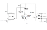
I have incorporated most of this expanded set of features in my latest uploaded schematic dimmer_modified_expanded.gif. However this schematic only shows one of the two heater sub-circuits, the other is identical to the one shown.

Also, I have omitted the PIC in the schematic, because I have not yet progressed to writing the PIC program. Please comment on the expanded circuit, particularly the isolation transformer and any other safety features. Finally, will the triac work as intended in the configuration shown?

EDIT: The isolation transformer should be 25VA, and not the 0.5VA shown in the schematic.
EDIT2: Put a 1.5A fastblow fuse in series with the load resistance, as some protection in the unlikely case of a short. I have omitted to show the bypass capacitors in the post voltage regulator lines. Just in case someone nitpicks about their absence.
 

Attachments

  • dimmer_modified_expanded.gif
    dimmer_modified_expanded.gif
    15.2 KB · Views: 343
Last edited:
That's looking better - but a mains transformer is no good, as you don't have mains across the primary - a simple option would be two transformers, back to back (primaries joined together), use the low voltage winding of one as the input, and of the other as the output. The first transformer needs to pass the entire load current, so choose a voltage/wattage that will do that, and you can choose the second transformer to step that up or down as required.

Or you could use a current transformer which is designed for the job, or a hall effect current sensor, again, designed for the job.
 
Thank you again Nigel. The Back to back transformer solution sounds good. Please provide me a hyperlink to a suitable Hall Effect current sensor if you have a particular one in mind. Will the triac work in the configuration shown? I have never used triacs before. Mosfets yes, but never triacs.
EDIT: Would this Hall Effect Current Sensor https://uk.rs-online.com/web/p/current-sensor-ics/6807131 be suitable?
 
Last edited:
That is a 5 amp job. If I understand your post correctly, your load will be milliamperes?
If my understanding is correct, then this device won’t have the required sensitivity.

EDIT: Honeywell used to make low current hall sensors. I used both their 40 and 200 mA devices.
Let me see if I can find the part number.
 
Thank you again Nigel. The Back to back transformer solution sounds good. Please provide me a hyperlink to a suitable Hall Effect current sensor if you have a particular one in mind. Will the triac work in the configuration shown? I have never used triacs before. Mosfets yes, but never triacs.
EDIT: Would this Hall Effect Current Sensor https://uk.rs-online.com/web/p/current-sensor-ics/6807131 be suitable?
When I did a quick google earlier, I was looking at some Texas ones, those types above (which are available mounted on modules from China - in fact I'm sat about three feet away from four of them sat in a draw) tend to be very high current. The Texas ones were much lower currents - have a look at TMCS1100A4 which gives 400mV per amp.
 
Thank you Schmitt & Nigel. While I was out browsing the aisles in the supermarket earlier this evening, I thought about the back-to-back transformer connection. It occurred to me, that if I used a trafo with split secondaries, with one secondary connected to the load circuit and the other connected across the sense resistor (with the high voltage primar-y/ies left unused), then we would achieve the same isolation with just a single trafo. Is this correct?

Either way, I found some inexpensive transformers with which to implement this idea: https://www.rapidonline.com/myrra-44235-ei42-encapsulated-pcb-transformer-230v-5va-0-6v-0-6v-88-5174 . At 5VA and 6v split secondary, I can go upto (0.5 x 5)/6 = 0.42A per 6v secondary winding. My maximum load current is 240V rms / 1000 ohms = 0.24A, so I have a safety margin of ( (0.42/0.24) - 1) x 100 = 75%. And at £1.36 (ex VAT) per transformer, no Hall effect sensor can compete on price.
 
Thank you Schmitt & Nigel. While I was out browsing the aisles in the supermarket earlier this evening, I thought about the back-to-back transformer connection. It occurred to me, that if I used a trafo with split secondaries, with one secondary connected to the load circuit and the other connected across the sense resistor (with the high voltage primar-y/ies left unused), then we would achieve the same isolation with just a single trafo. Is this correct?
No, the isolation is only between primary and secondaries - not between secondaries, so it would be unsafe.
 
OK - my only experience with hall effect sensors was in 1996, when I built an EPE project for an energy meter - it was a project in EPE Magazine, and used the 16C84, the original (and only at the time) EEPROM based PIC - and the one that got me started with PIC's. Notice it's pretty well zero spec list - not even a single ADC input, the project had to use an external one - however, there was an updated Mk2 version a few years later.

I even helped the author (and editor) John Becker on a couple of occasions, and was thus able to ask him why he rather bizarrely used a shareware assembler (that you were supposed to pay for) rather than the free official MPASM one - the answer amazed me, he'd never heard of MPASM :D

Anyway, here's a link to that long ago article (first part), it's on page 122 (or 36 of the PDF).


Second part - page 232 (66 of PDF)


I somehow doubt that sensor is available any more :D - and it was a bit vague about what it was anyway, I seem to recall it was available from RS Components?.
 
Purely as a matter of interest, I've been looking up the Mk2 version of the design - which actually uses a specific energy meter IC, and a simple shunt resistor to measure the mains current - hence the entire device is live, and thus mounted safely in a solid plastic box.

The first part, which includes the schematic is here:


But that's the latest issue the site provides :(

You can still download the firmware though, from the EPE legacy site, which is still written in TASM not MPASM :D
 
Reading your posts brought back memories. I cut my electroniker teeth on Everday Electronics/Popular Electronics/Radio & Wireless World and that rag from Ambit Electronics whose name I cannot remember, with pretty pictures of the innards of Japanese communication receivers - I recall a visually striking photo of a particularly densely populated, hand soldered Kenwood receiver PCB, crammed full with plls/crystal ladder filters etc, entitled "A thing of beauty & a joy forever". I vaguely recall that Messrs RA Penfold/RM Ramsden and Mr Rayner were the top contributors in those days. Must have been in early to mid-eighties. That's when Z80 projects/UVEproms/PET Microcomputers etc were the cutting edge of amateur digital electronics. When Maplin/Greenwald/TK Electronics were major component retailers.

Even looking at the ads for projects in the 2007 magazine link in your above post show how far we have come in the past 14 years. PIC LCD Display driver for 20 quid ? (Page 3) Bit steep compared to today. I also compared the ESR component prices on pg 7 with today's prices from ESR. Looking at 4017, BC547 & LM358 shows that even though prices have not changed much (though the LM358 has doubled in price), because of inflation, things are cheaper today than in 2007.

Speaking of energy meters, I remember the local council handing them out free, around 10 years ago. I mislaid mine.

EDIT: https://www.m5poo.co.uk/ambit-international/
 
Last edited:
If you put back to back voltage transformers, the core’s magnetization current will drown your current sample.

There are 1 amp doughnut type transformers, with an uncommitted hole where you may wind 10 or more turns of enamel wire. The sensitivity will increase proportionally with the number of turns. With 10 turns you would get a full scale of 100 mA.

But probably the best approach is, as Nigel mentioned a fully live circuit.
Communication to the external world could be done wirelessly with one of the many available protocols.
 
Good point Schmitt.

I've been thinking about this and have come up with a hypothetical solution, which I want to run past you.

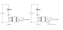
Please take a look at the diagram attached to this post. On the left of the diagram is the original back-to-back transformer proposal (split secondaries, only one of which is being used). The diagram on the right is the same as on the left but with a capacitor in series with the current sense resistor.

The impedance of this capacitor is roughly (or, if I'm lucky, exactly), equal to the negative impedance of the magnetising inductance of the primary winding. Since the capacitor's impedance will be reflected onto the primary, it will cancel out the magnetising inductance.

If say the magnetising inductance is 1H, its impedance will be 314.2 ohms, which equates to a 10.13uF say 10uF capacitor. If we use an 10uF electrolytic cap, rated at 16V, that should do fine.

The remaining problem is accounting for the capacitor's esr. The attached Panasonic FR series electrolytic cap datasheet shows us that we can attain low esr with the capacitor values under consideration. Comments please!
 

Attachments

  • Compensating Capacitor.gif
    Compensating Capacitor.gif
    16 KB · Views: 377
  • Panasonic FR_A Electrolytic Capacitors.pdf
    114.7 KB · Views: 340
I have finally had a chance to give 1996 EPE power meter circuit the detailed attention it deserved. What a complicated method of rectifying the current sensor output for the ADC !

But I did learn how to improve my stabilised bipolar power supply by comparing the EPE's (Part 1) Fig 3 on pg 123 with my dimmer_modified_expanded schematic (the EPE uses only 1 bridge compared to my 2).
 
Last edited:
There are better ways but you have to define all the requirements. i.e. specs with tolerances and range
 
Last edited:
I have finally had a chance to give 1996 EPE power meter circuit the detailed attention it deserved. What a complicated method of rectifying the current sensor output for the ADC !

But I did learn how to improve my stabilised bipolar power supply by comparing the EPE's (Part 1) Fig 3 on pg 123 with my dimmer_modified_expanded schematic (the EPE uses only 1 bridge compared to my 2).
Rather clever though, and avoids the voltage drop of diodes.
 
If this thing is a "one of", thing or proof of concept?
Can you use DC?
If you can, look into electronic loads. They can do constant R, I, P, V etc.

Where I worked, the system that was set up before me used Variacs, transformers and phase angle fired dual SCR units to heat 40V tantalum heaters.

Using DC actually increased the lifetime of the heaters as well.

I finally said we can scrap the technology and use a DC power supply controlled by a programmable temperature controller. We get "correct" metering with no extra work,

We also built the ultimate as a test case. 7 PID loops. We could do, P, I, V and T control on the fly with recipes. Essentially one variable was controlled and the other were limits. We added heat-up energy and that as an alarm. It protected against a misplaced thermocouple. This was back in the 1980's.
 
Status
Not open for further replies.

Latest threads

New Articles From Microcontroller Tips

Back
Top