Continue to Site

Welcome to our site!

Electro Tech is an online community (with over 170,000 members) who enjoy talking about and building electronic circuits, projects and gadgets. To participate you need to register. Registration is free. Click here to register now.

  • Welcome to our site! Electro Tech is an online community (with over 170,000 members) who enjoy talking about and building electronic circuits, projects and gadgets. To participate you need to register. Registration is free. Click here to register now.

PNP Transistor - base voltage higher than collector

Status
Not open for further replies.

Yobortsa

Member
Hi guys,

Is it ok for the base voltage driving a PNP transistor to be higher than the collector voltage?

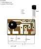
I'm trying to throw the input to a HS088 doorbell board (see attached) high from a microcontroller in place of the button shown on the schematic - have been testing with Arduino UNO in this case. I'm supplying the HS088 with regulated 3.3V from the Arduino and driving the Base of a PN200 transistor via a 470R resistor from one of the digital output pins which is 5V. It's working fine, but am I endangering the HS088 board by potentially putting 5V into it from the digital output driving the base? Or does this voltage drop over the resistor and I end up pushing only 3.3V into the HS088?

Any thoughts?

David
 

Attachments

  • HS088 Doorbell Board 1.PNG
    HS088 Doorbell Board 1.PNG
    195.9 KB · Views: 335
hi V,
The voltage will drop across the 470R, the Base to Emitter voltage if you measure it will ~0.7v.
Do you mean a PNP transistor.?
E

Do you have a simple sketch of the intended circuit.?
 
Here is a sketch of what I've set up:

upload_2017-3-3_19-25-15.png


The PN200 PNP transistor is in place of the switch shown on this diagram:

upload_2017-3-3_19-26-15.png
 
hi D,
I guess you know that with the Arduino output pin set to High , ie: 5V the PNP will be Off.?

When the output pin goes Low 0V the PNP will be On and the Bell/Buzzer will sound.

The approx -2V reverse bias on the PNP Base Emitter, when the output is is at +5V, should be OK.

E

BTW: Your circuit and the PCB layout do not match,?
 
Thanks Eric.

Yes, all is working; I just wanted to make sure the reverse bias is ok.

The diagram I've drawn only replaces the button and battery on the PCB layout - there is a second transistor on the board that drives the speaker, plus a couple of capacitors on the board also. Will work well as a remote doorbell in the shed when I'm the only one home and can't hear the house doorbell. I purchased these units on eBay and the HS-088 is what I found inside:

upload_2017-3-3_20-0-35.png


Regards,

David
 
hi David,
Is this what you are require.?

E
 

Attachments

  • A004.gif
    A004.gif
    27.7 KB · Views: 348
hi,
I would add a resistor so that the old switch input pin doesn't 'float', when the transistor is Off.
This would reduce the chance of a mis-operation due to electrical interference.
E
 
Well I'm much clearer on PNP transistors now. I now have a 1k resistor on the base of the transistor and a 4.7k pull-down resistor on the collector to ground to stop it floating. It seems to work fine - will leave it run for a day or so on test before soldering it up and installing.

Thanks for your help Eric :)
 
The reverse Base to Emitter breakdown voltage is shown on a transistor's data sheet, be PNP or NPN.
 
Thanks Mike. I now see it hidden in there - I assume I'm ready correctly that it's well within spec: Base being only 1.7V above Emitter.

upload_2017-3-4_16-56-17.png
 
Morning Y,
I assume that the 104 capacitor will be included as in the original circuit.?
The COB [ chip on board, the black blob] may not function correctly if the input is DC coupled.?
E
 

Attachments

  • A001.gif
    A001.gif
    16.2 KB · Views: 274
I can't be certain if there's a 104 capacitor, but there are two on the original PCB I've connected to - I simply replaced the switch (and only the switch) with the transistor. And it's been working fine for over 24hrs with the odd test ring every now and again. It's hooked up to my MQTT broker (Mosquitto on a RPi) so can be controlled remotely very easily. I guess I might be able to put the multimeter on the pad and test for capacitance. Might try that with a spare unit I have when I get home.
 
hi Y,
As it is working OK, I would suggest not making any changes.
A capacitor coupled input is often used where the circuit is expecting an 'edge' signal, some input circuits will not work correctly if held High or Low.

E
 
Status
Not open for further replies.

Latest threads

New Articles From Microcontroller Tips

Back
Top