Continue to Site

Welcome to our site!

Electro Tech is an online community (with over 170,000 members) who enjoy talking about and building electronic circuits, projects and gadgets. To participate you need to register. Registration is free. Click here to register now.

  • Welcome to our site! Electro Tech is an online community (with over 170,000 members) who enjoy talking about and building electronic circuits, projects and gadgets. To participate you need to register. Registration is free. Click here to register now.

Pls help, HT648L data not coming..

Status
Not open for further replies.

shobhit_goel10

New Member
Hi I am developing a circuit for college, which transmits the data from PC Parallel port..
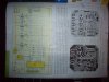
My connections are as follows:-


PC PARALLEL PORT ----> 8 RELAYS ----> HT 640 ----> RF TRANSMITTER

and

RF RECEIVER ----> HT648L ---->ULN 2803 ----> TWO STEPPER MOTORS.

I have connected an LED to th VT of HT648L.. The LED is glowing but there is no movement of motors..
I think the data is not coming on the HT648L data pins eu to some reason.

Can I please get some help as what may be the problem..

Thanks a lot..
 
Why do you have relays between the parallel port and the HT640?

I saw a similar circuit in a magazine. I think its for the protection of the PC Parallel Port. The relays each supply Vcc to the Data pins of HT640 whenever there is a '1' output from the Parallel port, otherwise they supply ground.

I think the Transmitter part is working fine..

What may be the problem at the receiver?

Thanks..
 
But relays?! If you need isolation use optoisolators not relays.
 
But relays?! If you need isolation use optoisolators not relays.

Yes sir you are right..I had thought the same..but I do not know and the transmitter and relays are all working fine, as I checked with a multimeter.

yes it is a design from Electronics For You magzine..

But what can be done at the receiving end?

Thanks..
 
By what method have you determined that the problem is at the receiving end? Just because the decoder is getting a valid signal does NOT mean that the data it's getting is correct. You can't use a relay to drive a stepper motor signal they can't switch fast enough, you need to get those relays out of that circuit and use either opto isolators or if it's possible directly connect it.
 
Can you post a link to the EFY article? is it free?

I dont think its free, but I have clicked a snapshot of the mag circuits..

The only changes I have done are

Used 8 relays-diode-transistor combination instead of the 4.
Used pin 2 to 9 of PC Parallel Port
ALL N/O 's to Vcc
All N/C's to Ground
AD10 to AD17 to all the COMs of relays
Inverted the diodes
HT640 instead of HT12E
As HT640 is active high, so connected TE accordingly..

HT648L instead of HT12D
Removed the not gates.
2 stepper motors.
Uln 2803 instead of 2003

Thanks a lot..
 

Attachments

  • Transmitter.JPG
    Transmitter.JPG
    1.1 MB · Views: 1,202
  • Receiver.JPG
    Receiver.JPG
    1.1 MB · Views: 771
By what method have you determined that the problem is at the receiving end? Just because the decoder is getting a valid signal does NOT mean that the data it's getting is correct. You can't use a relay to drive a stepper motor signal they can't switch fast enough, you need to get those relays out of that circuit and use either opto isolators or if it's possible directly connect it.

When I connect multimeter to the Dout and Din of both encoder and decoder, I get rapid voltage variations, when both circuits are on, constant voltage when off. So I thought transmission must be happening..

I will try to connect directly..

some circuits of HT640 and HT648L I found, in the file..
thanks..
 

Attachments

  • 8-BIT-RF2.GIF
    8-BIT-RF2.GIF
    19.9 KB · Views: 1,334
Last edited:
Status
Not open for further replies.

Latest threads

New Articles From Microcontroller Tips

Back
Top