Continue to Site

Welcome to our site!

Electro Tech is an online community (with over 170,000 members) who enjoy talking about and building electronic circuits, projects and gadgets. To participate you need to register. Registration is free. Click here to register now.

  • Welcome to our site! Electro Tech is an online community (with over 170,000 members) who enjoy talking about and building electronic circuits, projects and gadgets. To participate you need to register. Registration is free. Click here to register now.

please identify and define these transformer terminals for me?

Status
Not open for further replies.

sirmikeylikesit

New Member
**broken link removed**

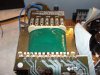
I have continuity between all pairs of labeled terminals except the first CT and the second CT does this indicate a bad transformer?
 
Perhaps you hit 'post' before you finished writing.

[edit] ahhh, picture posted, awaiting moderation? Interesting, found a hidden url in this post.

The CT terminals are center taps of the respective windings. They aren't connected together inside a normal transformer. The CT beteen the FL terminals should have continuity to them; between the POWER terminals same, and the CT between the REG terminals should have continuity to them.[/edit]

Here's the picture: https://sites.google.com/site/orotundindustries/work-space/transformer.JPG
 

Attachments

  • transformer.JPG
    transformer.JPG
    137.6 KB · Views: 164
Last edited:
what does the FL stand for?
 
Since NOOBIES cannot attach schematics or anything until a moderator passes it then maybe the entire NOOBIE post should be delayed from being seen.

It is frustrating to read a post that has its attached schematic held back.
 
what does the FL stand for?
perhaps internal convention followed by the designer
we , as user, can only identify them as three different center tapped windings.
any common connections found could either be thro' the circuit or possibly a fault inside the windings.
generally the transformer rewinder, by carefully watching during dismantling and makes a clone of it.
 
perhaps internal convention followed by the designer
.

the out puts are 3 isolated windings, supplying to external boards maked as power, FL, Reg, all are centre tapped. if there will be any reading between the sets (FL, CT, FL) , (Power CT Power) or (Reg CT Reg) when the transformer is pulled out, then its confirm that there is a internal fault.

power: may be for power amp board
Reg: may be to some regulator board
FL: may be for any lighting or else
 
.............

power: may be for power amp board
Reg: may be to some regulator board
FL: may be for any lighting or else
we can't just imagine. by the way where is this module used? a MW oven, washing machine ?
 
Last edited:
yes we dont know thats why i mentioned may be..., at the same time for sure its not for a MW oven or a washim machine, just have a look of the PCB on the picture, you can see line in/out sockets at far,thats why i am pretty sure its a board in a cassate player or any other with am amplifier. by the way FL mark is not for internal of transformer, its for external PCB tag.
 
FL is a higher voltage low current winding for the fluorescent display module on the appliance. Note the thin winding wire and low current PCB tracks.

POWER is very obviously lowish voltage high current based on the thick wire and high current tracks with very minimal isolation between tracks.

REG is the +/- 15v or so needed by the preamp etc.

Looking at the block of RCA connectors on the back panel and huge filter caps it's very obviously a power amp, based on mainly through hole components it looks like an older (late 80's or early 90's?) hifi amp.

Just power the transformer up and measure the AC voltages on its output pins.
 
Status
Not open for further replies.

Latest threads

New Articles From Microcontroller Tips

Back
Top