Continue to Site

Welcome to our site!

Electro Tech is an online community (with over 170,000 members) who enjoy talking about and building electronic circuits, projects and gadgets. To participate you need to register. Registration is free. Click here to register now.

  • Welcome to our site! Electro Tech is an online community (with over 170,000 members) who enjoy talking about and building electronic circuits, projects and gadgets. To participate you need to register. Registration is free. Click here to register now.

Please help with LED power supplies

Status
Not open for further replies.

alockrem

New Member
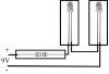
My father and I are building a golf ball display case and I decided to add some LEDs above each golf ball. I will most likely be using a 9v battery to power the LEDs, but I want the option to use a left over power supply if it's possible.

Most power supplies I found in my junk drawer are 5v, but 1 of them is has an output of 9v DC, which I believe is what I'm looking for. What I don't understand is the amps, which it says are 1.1 amps. What does that mean to me? Since it's a 9v power supply will it use the same resistors as a 9v battery or am I missing a part of this equation?

BTW - During my prototype of this project I used a 9v battery and 330 ohm resistors. It worked as expected. If possible, I would like to use the same resistors.

Thank you for any help.
 
You can get a lot more power out of that power supply by using the LEDs in series, but you would have to use different resistors, so that might be out.

Basically the 1.1A is the maximum amps the power supply is rated for. Going through the math I estimate each LED is pulling 16.4ma, which is a good number. Every LED/resistor you add is another 16.4. If you have 67 such pairs you would be pulling 1.1 amp, that is the max you could have. You really need to use a bit less, but I suspect this isn't going to be a problem.
 
Most power supplies I found in my junk drawer are 5v, but 1 of them is has an output of 9v DC, which I believe is what I'm looking for. What I don't understand is the amps, which it says are 1.1 amps. What does that mean to me? Since it's a 9v power supply will it use the same resistors as a 9v battery or am I missing a part of this equation?

If your 9V is typical it means that when suppling a current of 1.1 amps the voltage will be 9V, and if the current supplied(also called a load) is less than the 1.1 amps the voltage may be higher than the 9 volts.

A typical LED as seen in the attachment has a maximum current of 20mA or 0.02 amps. So 1 amp of current would power 50 of the LED's

It has been my expericence that even thou the LED is rated at a maximum current they are clearly visible a less current. I usually operate mine around 10mA or 0.01 amps.

If you are going to use the 9V battery for power you can connect LED in series, but still use a resistor to limit the current of the string. The color of the LED will determine the voltage of the LED. White for example are about 3V. To calculate the resistor needed add up the LED voltages, subtract it from the supply voltage, then divide the difference voltage by the current.

Example: 1 white LED, 9V battery LED current 0.01
9V-3V=6V 6V/0.01= 300 ohms. Since 300 ohms is not a standard value, use either a 330Ω or a 270 resistor.
 

Attachments

  • LED white.png
    LED white.png
    11.7 KB · Views: 156
Thank you both for your help.

I am obviously a beginner, so please forgive me if my terminology is incorrect. The design below is how the LEDs are going to be displayed. There will be about 30 of them.

Since I don't know all of the proper symbols I am using r for resistor (330 ohm) and D for LED (white, 20 mA).

--+---+---+---+---+--- (+)
r r r r r
| | | | |
D D D D D
--+---+---+---+---+--- (-)

Since these are using a single resistor for each LED it sounds like a 330 ohm resistor would be the proper value with a 9v power supply? If I read the responses correctly it also sounds like a 9v battery and a 9v power supply would use the same resistors.

Did I understand that correctly?
 
You didnot say what color the LED's are for sure. I assumed you are using white ones.
The 330Ω resistor may be to small of a value if you use the 9V power supply as the voltage may be some what higher than the indicated 9V.

I would try putting 2 LED's in series with the resistor and see how bright the LEDs on the 9V power supply. See attachment.
 

Attachments

  • LED hookup.JPG
    LED hookup.JPG
    26.5 KB · Views: 149
Yes. They are white ones.

I will try to put the 2 LEDs in series and see how well it works.

Thank you for all of your help.
 
I have a bunch of 300Ω, they are one of the standard sizes. My local source (Tanner's Electronics in Carrolton TX) has them for 3¢ each.

I'll attach a list of 5% ¼W resistors that can be had.

If you like what you already have I'd stick with it.

It is nice having a local outlet with resistors, especially at reasonable costs. I would be interested in any mail order equivalents.

I made a project of kitting them a while back.
 

Attachments

  • Resistor Standards.txt
    194 bytes · Views: 148
Last edited:
Hi alockrem,

you might reconsider the arrangement (and use) of current limiting resistors and the number of LEDs connected.

Please refer to the attached schematic and the calculations.

You might connect all LEDs with an individual current limiting resistor, dissipating lots of power in the resistors.

Connecting two LEDs in series does not only save 15 resistors (for 30 LEDs), but also reduces the total power loss by 2.7W (20mA LED current) respectively 1.35W (10mA LED current).

It doesn't matter much if you happen to have an own nuke power plant in the back garden, but even using that will save a lot of energy, thus taking care of less global warming. :D

Boncuk
 

Attachments

  • POWERDISSIPATION.gif
    POWERDISSIPATION.gif
    19.9 KB · Views: 144
Status
Not open for further replies.

Latest threads

New Articles From Microcontroller Tips

Back
Top