Continue to Site

Welcome to our site!

Electro Tech is an online community (with over 170,000 members) who enjoy talking about and building electronic circuits, projects and gadgets. To participate you need to register. Registration is free. Click here to register now.

  • Welcome to our site! Electro Tech is an online community (with over 170,000 members) who enjoy talking about and building electronic circuits, projects and gadgets. To participate you need to register. Registration is free. Click here to register now.

Please help review my Solar Racing Robot Circuit

Status
Not open for further replies.

brandon1213

New Member
Hi Everyone,

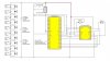
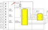
I'm an amateur roboticist trying to design my very first circuit. It is a circuit to power and control a little solar powered car with a motor for acceleration and servo for steering. It's probably a little ambitious for a first circuit, but I'm really determined to build it!

I've played around with some solar powered robot kits before, but this is my first time trying to design my own robot. All my knowledge has come from online tutorials I've been able to get my hands on. I'd really appreciate it if someone more experienced could take a look and critique my schematic. I want to get some advice on it and fix it before I order parts and start building.

**broken link removed**

Thanks a lot!

-Brandon
 
Well, the MAX856 has a typical startup voltage of 0.8V which could be as high as 1.8V. Your paralleled solar cells only provide 0.5V under full sunlight so the MAX856 will not start up. Try at least 4 smaller cells in series to give you 2V. LBI on the MAX856 should be connected to Vin. You should use the LBI/LBO pins to signal the MCU that the power is shaky and may go off soon.
 
Well, the MAX856 has a typical startup voltage of 0.8V which could be as high as 1.8V. Your paralleled solar cells only provide 0.5V under full sunlight so the MAX856 will not start up. Try at least 4 smaller cells in series to give you 2V. LBI on the MAX856 should be connected to Vin. You should use the LBI/LBO pins to signal the MCU that the power is shaky and may go off soon.

As for wiring them in series, if I wired four smaller .5v 50mA cells in series, and attached them in parallel to a larger .5v 500mA solar cell , would I get the equivalent of a single solar cell with 2v and 550mA?

So, I should connect the LBI on the MAX856 to the Vin on my MCU? I don't quite understand what the Low-Voltage Detector Input/Output does. Could you please explain?

Thanks for the help!
 
As for wiring them in series, if I wired four smaller .5v 50mA cells in series, and attached them in parallel to a larger .5v 500mA solar cell , would I get the equivalent of a single solar cell with 2v and 550mA?
No, you would get the equivalent of a 550ma 0.5V cell. Remember that the MAX856 is going to have to take 200ma at 1.65V to produce 100ma at 3.3V, but it'll need 330ma at 1V to produce 100ma at 3.3V (It'll be worse because it isn't 100% efficient). There is no free solar lunch for your bot.


So, I should connect the LBI on the MAX856 to the Vin on my MCU? I don't quite understand what the Low-Voltage Detector Input/Output does. Could you please explain?
The LBI pin is used to detect when the input voltage drops below a set level. A quote from the datasheet:
Low-Battery Output. An open-drain N-channel MOSFET sinks current when the voltage at LBI drops below 1.25V.
Low-Battery Input. When the voltage on LBI drops below 1.25V, LBO sinks current. If not used, connect to VIN.
So if you connect LBI to Vin (Solar cell output) and LBO to a pullup resistor on the 3.3V line as well as an interrupt pin on the MCU, then the MCU code can shut down the motors or otherwise conserve power when available light is low. If you use a resistive divider on the LBI pin you can adjust the voltage trigger point higher than 1.25V if needed.
 
There are a number of ways to use the L293, but that is certainly not one of them. The 1A 2A 3A and 4A are logic inputs. The Ys are the corresponding high current outputs. Let's concentrate on the 1/2 pair. Connect the motor + to 1Y and the motor - to 2Y.
Connect the 1A, the 2A and the 1,2 enable to 3 separate IO pins on the micro. Since you only have one power supply, connect both Vcc1 and Vcc2 to it. Connect ALL of the provided ground pins to ground, and use FAT runs when you layout a pcb. This is used as a heatsink for the chip. (a big ground plane underneath wouldn't hurt either).

Now, initially, all IO pins to be low. Keep 1,2 enable low, and set the other two pins for the direction you want the motor to spin in. 1A High and 2A low for forward, or 1A low and 2A high for reverse, and then bring 1,2 enable HI to turn the motor on. If 1A = 2A = high or low, the motor won't go (it'll have vcc or ground on both sides). To autobrake... leave the enable high and set 1A=2A (both high or both low) and this will short the motor winding causing it to lock up.

For two IO control instead of 3, you could tie 1A and 3A hi, tie 2A and 4A low; tie the motor + to 1Y and 4Y and the motor - to 2Y and 3Y. Tie the IO control lines to 1,2 enable and 3,4 enable. To go forward, enable 1,2. To go in reverse, enable 3,4. DO NOT enable them both at the same time, however, this would be bad and you would have a silicon volcano...
 
Thank you all for all the criticism and help. I've revised my circuit substantially.

Please take a look at it and let me know what you think.

https://s891.photobucket.com/albums...=view&current=SolarRacingRobotSchematic20.jpg

Note: More solar cells will be added in series depending on how much load my circuit has. I don't really know of how to measure the load of components like my motor without testing it out?

Something that has come to my attention is quiescent draw. If my power consumption rises above my incoming power, how do I detect this and what is the best way to address it? Should I be powering down my motors or uC until my storage caps are back to a sufficiently high voltage?
 
Last edited:
quiescent draw is what your circuit draws when it's in an "off" position...

It's physically impossible to consume more power than what is coming in, but you do store it in the supercaps, so I guess you can. In that case you would see a drop on the voltage of the caps. A resistor divider feeding into an ADC (analog to digital) pin on your micro can serve as a voltage status indicator, and you can shut the motors off until you see them charge back up, but mostly it will just run slower with the lower voltage, until you drain them enough to reset your micro... if you don't have an adc pin, feed it into a voltage comparator that can give you an interrupt on power loss... then you can monitor the level of the pin until it goes back to voltage good...

adding solar cells in series won't increase load capacity. It will make the motors run faster by uping the voltage. Don't forget there is an upper limit to the micro voltage... you might even want to put in a 5v or 3.3v regulator. The voltage coming off your solar cells doesn't want to be larger than the motor voltage. You add solar cells in parallel to up the capacity and deliver more current to drive bigger loads.
 
Last edited:
You have the unregulated power from the solar cells going to the AVCC on the uC. With the VCC supplied by the LM2940 this means that AVCC will always be greater than VCC. "AVCC must not differ more than ±0.3V from VCC".

When the solar cells are at, or below, their 5V (0.5V x 10) nominal output, the LM2940 isn't really regulating.
 
@Mike Odom

Sorry for the novice question, but what is a resistor divider and how is it being used in this circuit? Is it like a voltage divider? If i connect this to an ADC pin, do I also now need to connect something to the AREF pin on my MCU?

@mneary
Fixed the AVCC problem. Thanks!

https://i891.photobucket.com/albums/ac120/lockdown1289/SolarRacingRobotSchematic20-1.jpg

So, if I understand correctly, normal voltage regulators regulate the voltage downwards and increase current while boost converters regulate voltage upwards and lower current. Is there a way I can keep my voltage regulated at 5v if I start off with a higher source voltage than 5v that slowly decreases below 5v? This way I would be able to keep everything working until I'm able to charge my capacitors again, although at the cost of current.
 
@Mike Odom

Sorry for the novice question, but what is a resistor divider and how is it being used in this circuit? Is it like a voltage divider? If i connect this to an ADC pin, do I also now need to connect something to the AREF pin on my MCU?

I use AVR controllers and you have a variety of selections for AREF. External in, internal VCC, or internal VCC/2. I'm sure PICs have somewhat of the same feature, but if not then you can connect it to vcc. Yes, a resistor divider divides the voltage, so at 12V battery voltage you have 5 volts into your circuit, and at 9V battery you would read 3.75V.
@mneary
Fixed the AVCC problem. Thanks!

https://i891.photobucket.com/albums/ac120/lockdown1289/SolarRacingRobotSchematic20-1.jpg
So, if I understand correctly, normal voltage regulators regulate the voltage downwards and increase current while boost converters regulate voltage upwards and lower current. Is there a way I can keep my voltage regulated at 5v if I start off with a higher source voltage than 5v that slowly decreases below 5v? This way I would be able to keep everything working until I'm able to charge my capacitors again, although at the cost of current.

well, that is how voltage regulators work. you start with a higher voltage, then you regulate it down to the desired voltage. This is called a LINEAR regulator and they are not very efficient. You still have to dissipate an amount of power equal to your source voltage, not your delivery voltage. so if you start with 12v, regulate it down to 5v, and draw 1A, you dissipate 5W on your load but also 7W on the regulator, for 12W (or 12V x 1A) total. Switching regulators take a different approach. They push charge through an LC circuit to either up the voltage or lower the voltage, therefore, they deliver the correct amount of power with little used up in the process, so are much more efficient. For a 12V in, 5V 1A out switcher, the circuit will pull only about half an amp from the 12v supply, as 12V x .41666A = 5W. It will draw a little more to supply the quiescent current of the switching circuit plus there will (always) be losses in the parts (dissipated as heat), but they are about 80-90% efficient. This is known as a Buck converter, it lowers the voltage. One that raises the voltage is known as a boost converter. The source current will be larger than the supplied current to make up the power difference.

However, building a switching supply may be a little over your head.
But, if you switch the motors off when the voltage hits about 8V, then you should have enough left to idle your micro until they charge back up.
 
Looks a lot better. I would run the L293 power directly from the raw power and not through the regulator. Motors like to surprise regulators with spikes and surges. At your low power, it's not really bad for the regulator, but microprocessors don't like it.
 

Attachments

  • L293A..jpg
    L293A..jpg
    61.7 KB · Views: 301
here is a buck/boost I've used on numerous occasions. This design has been in my library for awhile, so I can't even tell you it's specs. It's probably overkill for what you are doing, but it's not too large, depending on how big your robot is. It has a couple of To-220s on it. I know it will give a rock steady output of 5V with less than 4v in as I (had to) use it on an auto starter controller for a diesel - generator set and when you crank the engine the 12V drops to less than 4. In it's current configuration I'm using it to drop 24 down to 12V. I know it'll source at least 2A @ 12V. It has an internal 5A switch. You probably won't need the heatsink. I'm embarrassed to say I can't tell you any more about it than you could find looking at the spec sheet... the original design was done over 15 years ago and I've been using it every since. You may be able to get a smaller switcher once you characterize your motors and determine your full load. To characterze the motors, hook them to a 12V source (or whatever your final full voltage out of your solar cells will be) through an ammeter and see what they draw. You can change the voltage output by adjusting R1/R2 ratio. See the data sheet. Caps C10-12 need to be low ESR (equiv. series resistance) as they are being fed current at high switching rates. I'm using Panasonic FC series. The FK series have even lower ESR.
 

Attachments

  • switcher..JPG
    switcher..JPG
    47.9 KB · Views: 300
  • 1230_converter on&.PDF
    138.7 KB · Views: 239
also add a .1uF capacitor to the output of your voltage regulator (Lm2940), as close to the output pin as possible. And another across the micro's power pins.
 
Will do.

I've gotten so much help from you guys, I feel like I should just be honest about what I am doing:

I am an undergraduate sophomore in college attempting to lead my school's first robotics team into the IEEE Southeastcon2010 Hardware competition:
**broken link removed**

I go to a school with no engineering department and a combined Math/CS department the size of a high school track team. As such, I've been spending probably 20hours a week teaching myself all I can about electronics. I realize now that I was naive and over-ambitious to think that I could do this all by myself given my complete lack of electronics experience, but I really wanted to accomplish something great for myself and my school. Time is short now, and although things don't look good I'm still working as hard as I can to design a working circuit for my team with only the recent help of kind folks online such as yourselves. I'm proud that I've gone a long way from lighting up my first LED on a breadboard just a month ago (wow, seems like that was a year ago), but I am still very afraid I might let down my school and supporting department.

I just wanted to say I really appreciate all the help you've given me in fixing my terrible circuit. I'll try my best to figure out this buck-boost converter circuit.
 
you don't need the buck/boost. I only supplied it because you said you might put one on. You really don't need it.
 
I would suggest you bring up your circuit in blocks. Do your solar array/power supply first. Then do your micro/motor control circuit. You can add the converter at any time later if you need it, but bring up one peice at a time and get that working, then go to the next. If time is short, you should do the things that NEED to be done first. That is power supply and robot control. You can enhance the rest later. Get a board built that you can start programming on. It's going to take you longer to write the code than you think.
 
Ok, that sounds like good advice. I still need a voltage regulator though to regulate my voltage to 5v correct? Because my MCU has an operating voltage of anywhere from 1.8V to 5.5V does that mean it will work with an unregulated voltage? My Ultrasonic sensor also needs a 5v input. As for power, I'm going to stick on as many .5v 250mA solar panels as possible on my robot.
 
Status
Not open for further replies.

Latest threads

New Articles From Microcontroller Tips

Back
Top