Continue to Site

Welcome to our site!

Electro Tech is an online community (with over 170,000 members) who enjoy talking about and building electronic circuits, projects and gadgets. To participate you need to register. Registration is free. Click here to register now.

  • Welcome to our site! Electro Tech is an online community (with over 170,000 members) who enjoy talking about and building electronic circuits, projects and gadgets. To participate you need to register. Registration is free. Click here to register now.

Please help, precision 1kHz sine filter

Status
Not open for further replies.
Hi again,

The theoretical THD came out to the following...

All resistors and caps and inductor as drawn:
0.00057 percent no load, 0.00091 percent with 1k load

All resistors and caps as drawn with shorted inductor:
0.00057 percent no load, 0.0010 with load


Three resistors 330 ohms and three caps 0.33uf and shorted inductor:
0.00037 percent with load, output drops somewhat

Inductor of 23mH with series resistance up to maybe 200 ohms (10 times larger inductance than the original) and second two resistors and caps as original with first cap around 1uf:
(so low in the neighborhood of 0.000015 percent with load, with decent output level too)

Can you try the three 330 ohm resistors with three 0.33uf caps next? That would save from having to buy an inductor, which doesnt do as much as it should for the cost of just being there at all. The inductor would do most when the circuit is tuned near 1kHz, but to get to that level and not load the output and still have decent output requires a larger value inductor.

Some notes:

1. It seems that if a 23mH inductor was available it might work much better because it would allow tuning near the target 1kHz without loading the output port pin too much.
2. It also seems that three 330 ohm resistors and three 0.33uf caps might work just as well as a 2.3mH inductor and other original values if the output drop can be tolerated. This would mean no inductor required.
3. For the hobby shop, perhaps this can be spec'd with and without the inductor and possibly with more than one value inductor (we could find one suitable). That would give the hobby person some choice as to how to build the output filter according to their needs and budget.
 
Last edited:
Hello again MrRB,

Ok, a harmonic analysis of the pattern and filtered pattern (R=220 ohms, C=0.22 uf) and filtered pattern with those values and 1k load resistance produced the following results:

Without filter:
THD=0.3 (up to 157th harmonic)

This doesn't seem quite right.

There are two common definitions of THD. The audio folks use: THD = (Total RMS of harmonics)/(Total RMS of full waveform)

The grid power people use: THD = (Total RMS of harmonics)/(RMS of Fundamental)

These two definitions approach the same value if the THD is small. I'll use the audio version.

I've attached two images showing a PWM approximation to a sine wave with different numbers of switching intervals. The RMS value of the sine wave being approximated is .5. The time axis is in radians.

Clearly, in both cases the RMS value of the full waveform is 1. In fact, the RMS value of this PWM approximation is exactly 1 no matter how many switching intervals there are.

Also, the peak value of the sine wave approximated by the PWM wave is about .707, so the RMS value of the fundamental component of the PWM wave is .5 and doesn't change with varying numbers of switching intervals.

This means that the RMS value of the harmonics, excluding the fundamental, is about .866, and the THD is about 87%. The THD apparently doesn't change as the number of switching intervals increases.

If a PWM waveform approximates a sine wave in such a manner that the peak of the approximated sine just doesn't get clipped, the lowest distortion of an unfiltered PWM approximated sine will occur under these circumstances and is about 71%.

If the magnitude of the approximated sine is less than this, the THD of the unfiltered PWM wave will be greater than 71%, and will not change with increasing numbers of switching intervals.

The THD of an unfiltered stepped approximation to a sine wave, on the other hand, does decrease with increasing numbers of switching intervals (and number of steps), and is much easier to filter.

It's quite easy to lock the frequency of a stepped sine approximation to a crystal oscillator. The per step amplitude error of a stepped approximation is quite low even without any filtering when the number of steps is large.
 

Attachments

  • PWM1.png
    PWM1.png
    2.8 KB · Views: 261
  • PWM2.png
    PWM2.png
    3.8 KB · Views: 247
... The theoretical THD came out to the following...

All resistors and caps and inductor as drawn:
0.00057 percent no load, 0.00091 percent with 1k load

All resistors and caps as drawn with shorted inductor:
0.00057 percent no load, 0.0010 with load

Those figures look excellent, I'm happy with that! :D 
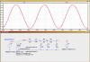
The inductor seems to make very little difference which is a little surprising as it makes a big difference in the hash after stage 1. I'll assume that is because all that hash is gone by stage 3 in both cases (with or without the inductor)?

...
Three resistors 330 ohms and three caps 0.33uf and shorted inductor:
0.00037 percent with load, output drops somewhat

Inductor of 23mH with series resistance up to maybe 200 ohms (10 times larger inductance than the original) and second two resistors and caps as original with first cap around 1uf:
(so low in the neighborhood of 0.000015 percent with load, with decent output level too)

Can you try the three 330 ohm resistors with three 0.33uf caps next? That would save from having to buy an inductor, which doesnt do as much as it should for the cost of just being there at all. The inductor would do most when the circuit is tuned near 1kHz, but to get to that level and not load the output and still have decent output requires a larger value inductor.
...

I tried heavier filtering with many parts values, including two 0.33 and two 0.33 plus 0.22 in some combinations. The result on the scope looked to be just as perfect shaped sine as before, but of course much lower amplitude.

Amplitude really is the cinch for this, as 2v p/p is an ideal value to be able to push audio stages to their limit and also allows some headroom for signal injecting into a lower impedance somewhere within an amp. One benefit of doing this with JUST a passive filter is that it is pretty bulletproof being originally driven from a PIC digital output pin. If its output is accidentally connected to say a 30v AC signal this will cause some small currents into the PIC output pin diodes or pin FETs but nothing is likely to be damaged or permanently changed because of the accident.

It was a little tricky to still get that 2v p/p output and still filter as much as possible within that constraint!

...
Some notes:
1. It seems that if a 23mH inductor was available it might work much better because it would allow tuning near the target 1kHz without loading the output port pin too much.
2. It also seems that three 330 ohm resistors and three 0.33uf caps might work just as well as a 2.3mH inductor and other original values if the output drop can be tolerated. This would mean no inductor required.
3. For the hobby shop, perhaps this can be spec'd with and without the inductor and possibly with more than one value inductor (we could find one suitable). That would give the hobby person some choice as to how to build the output filter according to their needs and budget.

I'm in complete agreement with everything there. A 23mH inductor would be ideal but is likely to be unavailable to most PIC hobbyists from junkbox parts. But it might be a nice option for people who want the extra precision.

Also the more heavily filtered the output is it can only get better, but at the cost of amplitude. Some people might be happier with the slightly better sine at only 1v p/p output. I just couldn't live with 1v p/p. :)

Maybe the best thing I can do is include your findings and recommendations on the web page, giving people those filter options?
 
Thank you very much for your technical input Electrician. :)

This doesn't seem quite right.
... This means that the RMS value of the harmonics, excluding the fundamental, is about .866, and the THD is about 87%. The THD apparently doesn't change as the number of switching intervals increases.

If a PWM waveform approximates a sine wave in such a manner that the peak of the approximated sine just doesn't get clipped, the lowest distortion of an unfiltered PWM approximated sine will occur under these circumstances and is about 71%.

If the magnitude of the approximated sine is less than this, the THD of the unfiltered PWM wave will be greater than 71%, and will not change with increasing numbers of switching intervals.
...

That all makes sense, inlcuding that the THD of the PWM remains constant regardless of interval number as it will always spend all its time at 100% or 0% (same error) and all its time is of course referenced to the same sine wave to calculate the error.

As for whether THD of the PWM is 30% or 71% I don't have a clue which calc is right but it seems logical the error is >50% as from any small period of the sine wave (as large as a PWM period) the PWM will extend to 100% and 0%...

Hopefully MrAl can clear this up?

...
The THD of an unfiltered stepped approximation to a sine wave, on the other hand, does decrease with increasing numbers of switching intervals (and number of steps), and is much easier to filter.

It's quite easy to lock the frequency of a stepped sine approximation to a crystal oscillator. The per step amplitude error of a stepped approximation is quite low even without any filtering when the number of steps is large.

I agree, a stepped DAC sine (which would normally be xtal locked) would be much easier to filter and starts with less THD at the source. :) But this project was an exercise in minimalism, ie; "Can someone just grab a PIC and a xtal and make a very precise sinewave?"

In that exercise there is a big payoff using the PWM as although it requires more filtering it has a great simplicity and (assuming accurate xtal locked PWM periods) the output signal is as exact a sine as the math lookup table. The PWM essentially allows the "perfect sinewave" to be generated directly at a PIC output pin, apart from the 50kHz hash which can easily be filtered out.

So the final part of the exercise became "Can a hobbyist throw together a simple RC or RLC filter from a few junkbox parts, and still get an excellent sinewave at useful amplitude?"

And I think it has reached a success or is very close to reaching a success, depending on how "perfect" a sine is needed...
 
Hello again MrRB and Electrician,


Electrician:
I agree a DAC type stepped pattern would be nice as before, but i thought the project was supposed to be as simple as possible. If MrRB is getting such a nice output with some small filtering why add the extra complexity?
For the THD percent i use the THD percent of the fundamental. Thus if we have a 1v output at 1kHz and we have 1 percent THD at 5kHz, then the fifth harmonic has a THD of 1 percent. The Total THD is the harmonic mean of all the harmonics up to a given harmonic number, not up to a certain number of switching intervals, so while a total THD of a given pattern may very well be 100 percent up to a given harmonic number it may be less. The reason for doing this in the first place is because it becomes impractical to work with exceedingly higher harmonics because in practice they get eaten up by various component responses that arent included in the pure mathematical calculations. As soon as some small filtering is used the higher harmonics go to very low levels because of the roll off characteristic.

MrRB:
As i was saying above, the harmonics of the raw pattern are difficult to estimate as we look at higher and higher frequencies (not switching cycles). The filtered pattern is a little more reasonable to work with but when there is an inductor involved that may throw the numbers off a little too because of the possible nonlinear character of the core material.
The numbers i provided are taking into account the harmonics up to the 157th but we could go higher of course if you like.

Yes, a 23mH or similar inductor wont be as easy to obtain and that was just more or less a suggestion. And yes, the name of the game is to filter the output and still get reasonable output amplitude, and that's why a larger inductor could help. A larger inductor allows a true bandpass type filter response. The difference between that kind of response and the kind we have now is that the kind we have now can only LOWER some harmonic levels, and that means the 1st harmonic (the one we want at 1khz) gets killed somewhat too depending on what -3db point we choose, but a true bandpass with the right inductor not only kills the upper harmonics (and lower if there is significant nonlinear response somewhere else in the system) but it can actually boost the fundamental, meaning more output than we put in in some cases. That means much bigger output.

That brings up another issue that we didnt get to yet. I assume you are using one single pin for the output, but have you considered using 2 pins instead? If the other pins arent doing anything anyway, you can convert this pattern into a bridged type pattern and get twice the amplitude for almost no work and no extra parts. The idea is to generate a dual pattern on two pins instead of one, and take the output from across the two pins instead of one pin and ground. That provides a double output amplitude signal level which when filtered, would be higher in amplitude too.
There's also the parallel pin possibility, to use two pins to drive the same filter node. That could provide lower output impedance, but i've never done this before so im not entirely sure about its success...just a thought here.
 
Hiya Mr Al,

The Total THD is the harmonic mean of all the harmonics up to a given harmonic number...

I agree that the sum of the roots of the normalized or non-normalized harmonics included in an evaluation following the standard IEEE, as I recall, is the recognized standard. Let the manufacturers of audio stuff eat cake!:D

What I'm really posting about are the configuration and values of components used in your evaluation to evaluate via LTSpice. Simply stated, I'm not able to come anywhere near your THD results with passive filtering by simulation. Is it an issue with LTSpice? I really don't know, but want to know to be able to trust the results of LTSpice. My best with a hybrid staggered 2nd order LP filter followed by a parallel resonator with MR DB's parts limitations is ~0.031% with a 1K load, a 150mΩ series resistance of the inductor and 155 harmonic sample.

So could you post a schematic with the values of the components for my evaluation using LTSpice? Also, did you use 50 or 51 slices of the 1kHz fundamental in your program? The only way I can get the 51kHz harmonic to rise to a significant level is with 51 slices, which turns to the 50th with 50 slices, and which appears to be an artifact of the slice repetition rate as I would expect.

Thanks in advance for your time.

Cheers,
Merv
 
Hello again MrRB and Electrician,


Electrician:
I agree a DAC type stepped pattern would be nice as before, but i thought the project was supposed to be as simple as possible. If MrRB is getting such a nice output with some small filtering why add the extra complexity?
For the THD percent i use the THD percent of the fundamental. Thus if we have a 1v output at 1kHz and we have 1 percent THD at 5kHz, then the fifth harmonic has a THD of 1 percent. The Total THD is the harmonic mean of all the harmonics up to a given harmonic number, not up to a certain number of switching intervals, so while a total THD of a given pattern may very well be 100 percent up to a given harmonic number it may be less. The reason for doing this in the first place is because it becomes impractical to work with exceedingly higher harmonics because in practice they get eaten up by various component responses that arent included in the pure mathematical calculations. As soon as some small filtering is used the higher harmonics go to very low levels because of the roll off characteristic.

Hiya Mr Al,

I agree that the sum of the roots of the normalized or non-normalized harmonics included in an evaluation following the standard IEEE, as I recall, is the recognized standard. Let the manufacturers of audio stuff eat cake!:D

What do you mean by "sum of the roots"? Do you mean "sum of the square roots"? And, the THD must surely be something more than just a sum; shouldn't it involve a ratio? Furthermore, "sum of the roots" isn't the same as "...harmonic mean of all the harmonics up to a given harmonic number" is it?

I am unable to find a source describing the calculation of THD to be: "The Total THD is the harmonic mean of all the harmonics up to a given harmonic number". Can either of you give me a link to such a description?

What I find is this: https://en.wikipedia.org/wiki/Total_harmonic_distortion

which is the definition used by the power engineering community.

The instruments commonly used to measure THD, such as:
**broken link removed**

**broken link removed**

make the measurement according to the first formula I gave.
 
...
Yes, a 23mH or similar inductor wont be as easy to obtain and that was just more or less a suggestion. And yes, the name of the game is to filter the output and still get reasonable output amplitude, and that's why a larger inductor could help. A larger inductor allows a true bandpass type filter response. The difference between that kind of response and the kind we have now is that the kind we have now can only LOWER some harmonic levels, and that means the 1st harmonic (the one we want at 1khz) gets killed somewhat too depending on what -3db point we choose, but a true bandpass with the right inductor not only kills the upper harmonics (and lower if there is significant nonlinear response somewhere else in the system) but it can actually boost the fundamental, meaning more output than we put in in some cases. That means much bigger output.
...

Point taken and was already understood! I did notice when I was testing that LC resonance had a tendency to destabilise or distort the 1kHz sine, I think this was some reaction with the low impedance digital nature of the PWM source (PIC FETs) and I settled on a largely lossy RC filter (which was more stable) as it seemed unwise to generate a mathematically good sine at source and then distort it with a filter resonance!

I'll make sure to include your suggestion for the bigger inductor on the web page write up which is almost written now. :)

...
That brings up another issue that we didnt get to yet. I assume you are using one single pin for the output, but have you considered using 2 pins instead? If the other pins arent doing anything anyway, you can convert this pattern into a bridged type pattern and get twice the amplitude for almost no work and no extra parts. The idea is to generate a dual pattern on two pins instead of one, and take the output from across the two pins instead of one pin and ground. That provides a double output amplitude signal level which when filtered, would be higher in amplitude too.

Yes I considered that after you mentioned number of pins in post #15. The problem is that the cheap end PICs like the 16F628 I used had only one PWM output pin. The next step up in PIC 18F series can have 2 complimentary PWM pins, but that step up in technology will limit some hobby people again. The PIC 18F series would also allow faster and/or higher resolution PWM so it might be an option for a future project...

But then just how good does that sine need to be? :D

MRCecil said:
...
What I'm really posting about are the configuration and values of components used in your evaluation to evaluate via LTSpice. Simply stated, I'm not able to come anywhere near your THD results with passive filtering by simulation. Is it an issue with LTSpice? I really don't know, but want to know to be able to trust the results of LTSpice. My best with a hybrid staggered 2nd order LP filter followed by a parallel resonator with MR DB's parts limitations is ~0.031% with a 1K load, a 150mΩ series resistance of the inductor and 155 harmonic sample.
...

MRCecil, could you please re-run the LTSpice THD figures with the exact filter I showed in post #16 but WITHOUT the inductor and with no load? That gave a very nice result on the scope, and removes any distortion that may be added in the simulator from LC resonance, and removes distortion from the 1k load. Maybe that could act as a "base point" for comparing THD figures with MrAl too, as it removes any complexity added by the inductor.
 
Last edited:
Hello again MrRB, MRCecil, and Electrician,

I am replying to three different posts here...


MrRB:
With the 2 pin version i was assuming you would do a bang bang type output, not rely on any PWM periferal built into the chip. I figured a bang bang output would not limit the chip type at all.

MRCecil:
What are you using to generate the pulse pattern?
Also, what is the exact configuration of your parts and their values?
Im not sure what you mean by a schematic because all i did was use MrRB's values for the filter and generated the pattern using a program that reads the numerical values of his published values list and makes a pulse pattern out of it. If our numbers dont agree we can look into this further and see why they dont agree as you suggest.
Im also not sure what you mean by "50 or 51 slices of the 1kHz fundamental". I took the numbers that MrRB published and used them, so that would mean 25 periods above zero and 25 periods below zero, if that helps.
Since we are seeing a difference in results that may differ very greately (as with the 50th) i would suggest that we start with a much much simpler pattern with only a couple switch transistions per cycle and compare results with that first and go from there. The new pattern would be:

Positive half cycle: 0 1 0 1 0
Negative half cycle: 0 -1 0 -1 0
Both: 0 1 0 1 0 0 -1 0 -1 0

The timing would be as:
t=0.0ms 0
t=0.1ms 1 (switches to 1)
t=0.2ms 0 (switches to 0)
t=0.3ms 1
t=0.4ms 0
t=0.5ms 0
t=0.6ms -1 (switches to -1)
t=0.7ms 0 (switches to 0)
t=0.8ms -1
t=0.9ms 0
t=1.0ms (repeat above from t=0ms)

This is a very simple pattern and is easy to evaluate.


Electrician:
The definitition i use is the harmonic mean, which is:
THD=sqrt(v2^2+v3^2+v4^2+...+vInf^2)/v1

however for the filtered and even unfiltered pattern it is common to ignore very high frequencies as i mentioned previously, giving:
THD=sqrt(v2^2+v3^2+v4^2+...+vN^2)/v1

and the reason this works is because for almost any filter (except one designed just to void this rule for some reason) we end up with a filtered THD that approaches some limit of THD as the frequencies under consideration exceed some harmonic N. In other words:
THD(N)=THD(N+1)=THD(N+2)=THD(N+3)=THD(inf) approximately.
I chose N=157 as N=257 for example produces almost the same results, but can go higher if necessary.
 
Last edited:
hi Al,
Have been following this thread, I would like to add my bit to the mix..

I used a 50KHz based PWM drive, to create a 1KHz sine wave , using RB's circuit.

I added a 1KHz sine reference source, which I shifted into phase with filter output.

The two traces overlay almost perfectly.
 

Attachments

  • RB1.gif
    RB1.gif
    38.5 KB · Views: 262
Hello again MrRB, MRCecil, and Electrician,

I am replying to three different posts here...


MrRB:
With the 2 pin version i was assuming you would do a bang bang type output, not rely on any PWM peripheral built into the chip. I figured a bang bang output would not limit the chip type at all.

MRCecil:
What are you using to generate the pulse pattern?
Also, what is the exact configuration of your parts and their values?
Im not sure what you mean by a schematic because all i did was use MrRB's values for the filter and generated the pattern using a program that reads the numerical values of his published values list and makes a pulse pattern out of it. If our numbers dont agree we can look into this further and see why they dont agree as you suggest.
Im also not sure what you mean by "50 or 51 slices of the 1kHz fundamental". I took the numbers that MrRB published and used them, so that would mean 25 periods above zero and 25 periods below zero, if that helps.
Since we are seeing a difference in results that may differ very greatly (as with the 50th) i would suggest that we start with a much much simpler pattern with only a couple switch transitions per cycle and compare results with that first and go from there. The new pattern would be:

(see attached drawing)
Positive half cycle: 0 1 0 1 0
Negative half cycle: 0 -1 0 -1 0
Both: 0 1 0 1 0 0 -1 0 -1 0

The timing would be as:
t=0.0ms 0
t=0.1ms 1 (switches to 1)
t=0.2ms 0 (switches to 0)
t=0.3ms 1
t=0.4ms 0
t=0.5ms 0
t=0.6ms -1 (switches to -1)
t=0.7ms 0 (switches to 0)
t=0.8ms -1
t=0.9ms 0
t=1.0ms (repeat above from t=0ms)

This is a very simple pattern and is easy to evaluate.


Electrician:
The definitition i use is the harmonic mean, which is:
THD=sqrt(v2^2+v3^2+v4^2+...+vInf^2)/v1

however for the filtered and even unfiltered pattern it is common to ignore very high frequencies as i mentioned previously, giving:
THD=sqrt(v2^2+v3^2+v4^2+...+vN^2)/v1

and the reason this works is because for almost any filter (except one designed just to void this rule for some reason) we end up with a filtered THD that approaches some limit of THD as the frequencies under consideration exceed some harmonic N. In other words:
THD(N)=THD(N+1)=THD(N+2)=THD(N+3)=THD(inf) approximately.
I chose N=157 as N=257 for example produces almost the same results, but can go higher if necessary.
 

Attachments

  • Pattern-01.gif
    Pattern-01.gif
    4.6 KB · Views: 245
Last edited:
What do you mean by "sum of the roots"? Do you mean "sum of the square roots"? And, the THD must surely be something more than just a sum; shouldn't it involve a ratio? Furthermore, "sum of the roots" isn't the same as "...harmonic mean of all the harmonics up to a given harmonic number" is it?

I am unable to find a source describing the calculation of THD to be: "The Total THD is the harmonic mean of all the harmonics up to a given harmonic number". Can either of you give me a link to such a description?

I think it's obvious that I wasn't clear so let me restate. THD can be determined using either the actual recorded value of the fundamental and n harmonics or by using their normalized values. In the first case, it is a matter finding the root of the sum of the squares of Vn2, Vn3, Vn4...Vn divided by Vn1. If one normalizes the columnar data to the fundamental, the process is the same with a division by Vn1, which would be equal to 1. Yes there is a ratio involved in the computation, but to be sure, every number can be divided by 1.

My humble apologies for misstating my intended message to another.

Cheers
 
(see attached drawing)
Positive half cycle: 0 1 0 1 0
Negative half cycle: 0 -1 0 -1 0
Both: 0 1 0 1 0 0 -1 0 -1 0

Pardon me if I'm missing something here, but if you're trying to create a sine wave (even a degenerate one), shouldn't your pattern be

0 1 2 1 0 -1 -2 -1 0

(or normalized to 1: 0 0.5 1 0.5 0 -0.5 -1 -0.5 0)

or was this just a throwaway example?
 
Pardon me if I'm missing something here, but if you're trying to create a sine wave (even a degenerate one), shouldn't your pattern be

0 1 2 1 0 -1 -2 -1 0

(or normalized to 1: 0 0.5 1 0.5 0 -0.5 -1 -0.5 0)

or was this just a throwaway example?

hi,
Just in case Al is not around, the pattern he shows is a binary pattern of the base PWM.
 
Hi again,

MRCecil:
Please read post #31 where i posted a much simpler pattern so we can compare our analysis results.

Carbon:
The pattern i suggested:
0p0p00n0n0 (p=1, n=-1)

is simply a very simple pattern that can be used to compare our analysis methods. This pattern was chosen because it was a little more complicated than a square wave but yet simple enough to allow a quite simple proof that the amplitudes of the harmonics analysis results are the true amplitudes. We can generate an approximate pattern using the harmonics once we know what they are. If we dont get the harmonics right, we will get a very different pattern, but if we get them right, using some of the lower order harmonics we can generate a pattern that gets closer and closer to that original test pattern as we use higher and higher harmonics for the pattern generation (instead of using pulses as the real pattern is generated). It's a graphical technique that can prove whether we are doing this right or not. It has nothing to do with a sine wave however, it's just a simple test pattern that's all.
 
Last edited:
Hello again MrRB, MRCecil, and Electrician,

I am replying to three different posts here...


Electrician:
The definitition i use is the harmonic mean, which is:
THD=sqrt(v2^2+v3^2+v4^2+...+vInf^2)/v1

This expression doesn't seem to be the same as the common definition of the harmonic mean: https://mathworld.wolfram.com/HarmonicMean.html

Can you show me how your expression is the same as the harmonic mean given at the above URL?

however for the filtered and even unfiltered pattern it is common to ignore very high frequencies as i mentioned previously, giving:
THD=sqrt(v2^2+v3^2+v4^2+...+vN^2)/v1

and the reason this works is because for almost any filter (except one designed just to void this rule for some reason) we end up with a filtered THD that approaches some limit of THD as the frequencies under consideration exceed some harmonic N. In other words:
THD(N)=THD(N+1)=THD(N+2)=THD(N+3)=THD(inf) approximately.
I chose N=157 as N=257 for example produces almost the same results, but can go higher if necessary.

In post #15, you said: "Without filter:
THD=0.3 (up to 157th harmonic)"

I think the OP's pattern gives much higher THD than 0.3 (percent) even with harmonics only up to the 157th taken into account.
 
Hello again Electrician,


I have to apologize as i often call that calculation a "harmonic mean" because it's similar to and invert hyperharmonic mean, but strictly speaking those definitions are not universal as you noticed. A better definition is simply the Norm/Fundamental, where the Norm is the norm of harmonics not including the fundamental:
THD=sqrt(v2^2+v3^2+v4^2+...+vN^2)/v1

To clear things up please refer to that formula above.
Also, i dont often worry about the pattern harmonics too much because they have little bearing on the final output which always gets some filtering as well as rise and fall time considerations which take the higher ones down too. You're right in that the true raw pattern is higher than that and i'll update my formula to reflect that. All of these kinds of patterns will have very nasty non filtered harmonics.

I was hoping that anyone here that wanted to test their methods would use that much simpler pattern i had posted so that we can compare notes. An even simpler pattern is to just use the first pulse in each half cycle, which gives only one positive pulse from 0.1ms to 0.2ms and one negative pulse from 0.6ms to 0.7ms. Would be nice to compare calculations using both of these patterns.
 
Last edited:
MRCecil, could you please re-run the LTSpice THD figures with the exact filter I showed in post #16 but WITHOUT the inductor and with no load? That gave a very nice result on the scope, and removes any distortion that may be added in the simulator from LC resonance, and removes distortion from the 1k load. Maybe that could act as a "base point" for comparing THD figures with MrAl too, as it removes any complexity added by the inductor.

Here you go. The table in the scroll box below is the result of the configuration you noted.

Code:
Fourier components of V(out)						     DC component:0.98498							
							
Harmonic	Frequency	          Fourier 		Normalized	Normalized
Number 	[Hz]   		Component	         Component	          Phase [deg]
1	1.00E+03		4.76E-01		1.00E+00		    0.00°
2	2.00E+03		1.92E-04		4.04E-04		  -97.99°
3	3.00E+03		8.55E-05		1.80E-04		 -241.81°
4	4.00E+03		6.14E-05		1.29E-04		   15.04°
5	5.00E+03		4.03E-05		8.46E-05		  -89.47°
6	6.00E+03		3.63E-06		7.64E-06		 -191.11°
7	7.00E+03		5.69E-07		1.20E-06		  -52.12°
8	8.00E+03		1.87E-06		3.93E-06		 -190.44°
9	9.00E+03		1.38E-06		2.91E-06		   46.96°
10	1.00E+04		1.55E-06		3.26E-06		  -20.51°
11	1.10E+04		1.33E-07		2.79E-07		 -274.98°
12	1.20E+04		4.73E-07		9.95E-07		   39.57°
13	1.30E+04		4.21E-07		8.85E-07		   47.61°
14	1.40E+04		7.70E-07		1.62E-06		 -284.49°
15	1.50E+04		5.36E-07		1.13E-06		 -261.24°
16	1.60E+04		9.96E-08		2.10E-07		 -100.10°
17	1.70E+04		5.28E-07		1.11E-06		 -261.31°
18	1.80E+04		4.41E-07		9.26E-07		   69.65°
19	1.90E+04		5.49E-07		1.15E-06		 -281.09°
20	2.00E+04		9.79E-08		2.06E-07		   63.39°
21	2.10E+04		3.55E-07		7.46E-07		 -181.31°
22	2.20E+04		4.95E-07		1.04E-06		 -183.90°
23	2.30E+04		4.17E-07		8.77E-07		 -174.50°
24	2.40E+04		1.85E-07		3.88E-07		 -233.47°
25	2.50E+04		1.21E-07		2.54E-07		  -27.73°
26	2.60E+04		2.27E-08		4.77E-08		  -81.27°
27	2.70E+04		2.28E-07		4.79E-07		 -140.83°
28	2.80E+04		3.39E-07		7.14E-07		 -176.03°
29	2.90E+04		2.73E-07		5.74E-07		 -137.35°
30	3.00E+04		3.32E-07		6.97E-07		 -178.64°
31	3.10E+04		3.24E-07		6.81E-07		 -154.40°
32	3.20E+04		3.83E-07		8.06E-07		  -46.50°
33	3.30E+04		4.84E-07		1.02E-06		    2.57°
34	3.40E+04		4.55E-07		9.57E-07		  -61.33°
35	3.50E+04		3.19E-07		6.71E-07		 -122.73°
36	3.60E+04		3.47E-07		7.30E-07		  -97.41°
37	3.70E+04		2.10E-07		4.42E-07		 -269.62°
38	3.80E+04		2.53E-07		5.32E-07		  -22.59°
39	3.90E+04		7.32E-07		1.54E-06		    5.85°
40	4.00E+04		4.25E-07		8.94E-07		    5.82°
41	4.10E+04		1.25E-07		2.62E-07		 -285.14°
42	4.20E+04		3.13E-07		6.58E-07		 -170.18°
43	4.30E+04		1.32E-07		2.78E-07		 -260.56°
44	4.40E+04		2.73E-07		5.74E-07		 -242.86°
45	4.50E+04		2.80E-07		5.89E-07		   34.11°
46	4.60E+04		2.65E-07		5.56E-07		  -47.02°
47	4.70E+04		2.39E-07		5.03E-07		 -110.84°
48	4.80E+04		4.88E-06		1.03E-05		 -284.67°
49	4.90E+04		1.21E-04		2.54E-04		 -105.16°
50	5.00E+04		2.76E-04		5.80E-04		  -11.09°
51	5.10E+04		1.06E-04		2.22E-04		 -284.30°
52	5.20E+04		3.97E-06		8.34E-06		   73.81°
53	5.30E+04		5.00E-07		1.05E-06		    2.27°
54	5.40E+04		2.97E-07		6.24E-07		 -162.45°
55	5.50E+04		3.98E-07		8.36E-07		 -207.15°
56	5.60E+04		1.52E-07		3.20E-07		 -284.45°
57	5.70E+04		2.86E-07		6.01E-07		   44.05°
58	5.80E+04		3.44E-07		7.23E-07		  -35.49°
59	5.90E+04		1.42E-07		2.99E-07		  -33.77°
60	6.00E+04		2.27E-07		4.78E-07		 -120.41°
61	6.10E+04		1.04E-07		2.18E-07		 -214.94°
62	6.20E+04		4.23E-07		8.90E-07		 -252.88°
63	6.30E+04		5.22E-07		1.10E-06		 -241.35°
64	6.40E+04		1.62E-07		3.39E-07		 -239.86°
65	6.50E+04		1.08E-07		2.27E-07		  -19.82°
66	6.60E+04		1.38E-07		2.89E-07		 -159.60°
67	6.70E+04		7.29E-08		1.53E-07		  -39.95°
68	6.80E+04		3.52E-07		7.40E-07		 -230.28°
69	6.90E+04		2.10E-07		4.42E-07		 -121.18°
70	7.00E+04		2.45E-08		5.14E-08		 -208.48°
71	7.10E+04		2.21E-07		4.64E-07		 -120.21°
72	7.20E+04		2.45E-07		5.16E-07		  -61.12°
73	7.30E+04		2.56E-07		5.38E-07		  -47.63°
74	7.40E+04		1.10E-07		2.32E-07		 -280.13°
75	7.50E+04		1.72E-07		3.62E-07		 -130.86°
76	7.60E+04		1.04E-07		2.18E-07		    7.57°
77	7.70E+04		9.69E-08		2.04E-07		  -14.78°
78	7.80E+04		3.24E-07		6.81E-07		  -68.26°
79	7.90E+04		3.47E-07		7.29E-07		  -90.04°
80	8.00E+04		4.71E-07		9.90E-07		  -94.82°
81	8.10E+04		2.94E-07		6.18E-07		 -277.88°
82	8.20E+04		1.67E-07		3.51E-07		   44.93°
83	8.30E+04		4.86E-07		1.02E-06		   46.66°
84	8.40E+04		1.05E-07		2.21E-07		   36.53°
85	8.50E+04		2.77E-07		5.82E-07		   11.38°
86	8.60E+04		1.52E-07		3.19E-07		  -37.62°
87	8.70E+04		3.72E-07		7.83E-07		   26.20°
88	8.80E+04		3.42E-07		7.18E-07		   69.91°
89	8.90E+04		4.60E-07		9.67E-07		 -250.81°
90	9.00E+04		2.36E-07		4.96E-07		 -229.73°
91	9.10E+04		2.11E-07		4.44E-07		 -120.33°
92	9.20E+04		4.29E-07		9.02E-07		 -185.40°
93	9.30E+04		2.68E-07		5.63E-07		 -139.48°
94	9.40E+04		4.06E-07		8.53E-07		 -220.02°
95	9.50E+04		1.74E-07		3.66E-07		   39.78°
96	9.60E+04		1.21E-07		2.54E-07		   37.46°
97	9.70E+04		1.30E-07		2.74E-07		 -262.13°
98	9.80E+04		3.06E-07		6.43E-07		 -278.42°
99	9.90E+04		1.49E-06		3.14E-06		 -275.48°
100	1.00E+05		3.38E-06		7.10E-06		 -105.36°
101	1.01E+05		2.15E-06		4.53E-06		   36.23°
102	1.02E+05		3.60E-07		7.57E-07		 -119.16°
103	1.03E+05		2.22E-07		4.66E-07		 -164.77°
104	1.04E+05		1.14E-07		2.39E-07		   17.24°
105	1.05E+05		6.82E-08		1.43E-07		  -30.60°
106	1.06E+05		3.40E-07		7.14E-07		  -86.75°
107	1.07E+05		7.31E-08		1.54E-07		 -183.06°
108	1.08E+05		4.13E-07		8.67E-07		 -194.47°
109	1.09E+05		2.03E-07		4.27E-07		 -245.27°
110	1.10E+05		2.96E-07		6.22E-07		 -268.99°
111	1.11E+05		2.03E-07		4.27E-07		 -246.89°
112	1.12E+05		1.83E-07		3.85E-07		 -109.94°
113	1.13E+05		3.67E-07		7.71E-07		 -103.99°
114	1.14E+05		1.13E-07		2.37E-07		 -195.83°
115	1.15E+05		3.17E-07		6.67E-07		 -148.74°
116	1.16E+05		2.70E-07		5.69E-07		 -264.47°
117	1.17E+05		1.16E-07		2.44E-07		 -150.38°
118	1.18E+05		2.78E-07		5.84E-07		  -55.77°
119	1.19E+05		4.80E-07		1.01E-06		 -119.71°
120	1.20E+05		2.99E-07		6.29E-07		  -68.12°
121	1.21E+05		2.15E-07		4.52E-07		   70.51°
122	1.22E+05		2.73E-07		5.74E-07		   68.76°
123	1.23E+05		2.27E-08		4.78E-08		 -245.33°
124	1.24E+05		3.16E-07		6.65E-07		  -40.48°
125	1.25E+05		2.02E-07		4.26E-07		 -273.85°
126	1.26E+05		2.17E-07		4.55E-07		  -55.64°
127	1.27E+05		2.23E-07		4.70E-07		  -20.90°
128	1.28E+05		2.38E-07		5.00E-07		  -30.93°
129	1.29E+05		1.37E-07		2.88E-07		   28.30°
130	1.30E+05		8.84E-08		1.86E-07		   70.71°
131	1.31E+05		2.79E-07		5.86E-07		    1.79°
132	1.32E+05		3.22E-07		6.78E-07		   63.94°
133	1.33E+05		1.78E-07		3.74E-07		 -150.81°
134	1.34E+05		3.21E-07		6.75E-07		 -277.35°
135	1.35E+05		3.38E-07		7.11E-07		   62.71°
136	1.36E+05		3.25E-07		6.83E-07		   48.13°
137	1.37E+05		1.06E-07		2.24E-07		 -205.34°
138	1.38E+05		1.05E-07		2.22E-07		 -148.08°
139	1.39E+05		3.89E-07		8.18E-07		 -168.19°
140	1.40E+05		2.34E-07		4.91E-07		 -224.53°
141	1.41E+05		2.83E-07		5.95E-07		 -163.44°
142	1.42E+05		5.24E-08		1.10E-07		   -2.45°
143	1.43E+05		7.99E-08		1.68E-07		  -35.96°
144	1.44E+05		3.64E-07		7.66E-07		  -15.65°
145	1.45E+05		1.02E-07		2.13E-07		  -87.86°
146	1.46E+05		1.34E-07		2.82E-07		 -167.42°
147	1.47E+05		1.77E-07		3.73E-07		 -135.64°
148	1.48E+05		2.01E-07		4.22E-07		  -21.60°
149	1.49E+05		5.90E-07		1.24E-06		 -122.84°
150	1.50E+05		4.83E-06		1.02E-05		  -36.82°
151	1.51E+05		2.79E-06		5.87E-06		   60.94°
152	1.52E+05		5.69E-07		1.20E-06		 -282.52°
153	1.53E+05		5.91E-07		1.24E-06		 -240.02°
154	1.54E+05		9.92E-08		2.09E-07		  -19.07°
155	1.55E+05		2.52E-07		5.30E-07		  -67.14°
156	1.56E+05		8.47E-08		1.78E-07		 -128.93°
157	1.57E+05		3.37E-07		7.09E-07		 -140.71°
158	1.58E+05		1.89E-07		3.98E-07		 -170.23°
Total Harmonic Distortion: 0.081863%


As you can see, the THD is ~0.082% unloaded. With a 10k load it's ~0.089%; 5k it's ~0.093%; at 1k it's ~0.143%. The two issues I see are the filter is very lossy and the 50khz "carrier" at 50kHz and "sidebands" at 49 & 51kHz. It appears to me there is not enough roll-off to whack down those harmonics.

I'll post the schematic to display the mock PIC used to generate the input as I would like you to confirm that is a close approximation to the PIC output you have in the plot of the output I'll also post, and because Mr AL was interested in how I was generating the input too.

Also, I will post the FFT of the output so you can see the actual spectrum.
 

Attachments

  • PIC2_FFT.jpg
    PIC2_FFT.jpg
    273.5 KB · Views: 233
  • PIC2_IO Plot.jpg
    PIC2_IO Plot.jpg
    288.7 KB · Views: 249
  • PIC2.jpg
    PIC2.jpg
    91.9 KB · Views: 242
Hi Mr Al,

Yes, I'm very familiar with the basics. What I was curious about was the pulse rate of the "carrier" that "slices" the 1kHz. The first time I encountered something similar to this was about 40 years ago in my tech days on a US Army time diversity phone Rx/Tx field terminal from the 1950's era;
I was out of the NAVY then and working at an Army depot repair facility; Go Navy!

I was asking because you mentioned the 51st harmonic a few times and I was not getting that same response with a 50kHz square wave. In my post #38 I think I included everything you asked for. If I left anything out, let me know.
 
Hello MRCecil,

What do you mean you are not getting the 51st harmonic with a 50kHz square wave? I dont think i said that you would :)
What i did say is that you would see the 49th and the 51st harmonic if you generate the pattern that MrRB was talking about. Using a pulsing carrier and sine wave is not the same thing as using an actual pulsing pattern that goes from 0 to 1 or from 0 to 1 and from -1 to 0 for the negative half cycle. It is possible to completely cancel the 50th harmonic even though the pattern has 50 switching periods in it. I was going to show this same behavior with another wave too which is much simpler to generate and analyze. If you like, i can post an asc file for you to look at that generates the simple pattern and you can see for yourself.

While im waiting for you guys to reply again (and i'd like to hear some results on the simple pattern too eventually) im going over my own program and calculations just to make sure. One thing i did find already is that i was using a pattern that goes from 0 to 0.5 and from -0.5 to 0, rather than the one that goes from 0 to 1. In other words, i was assuming a 2 pin output pattern, which can be used to cancel many of the harmonics and make a really nice pattern.
 
Status
Not open for further replies.

Latest threads

New Articles From Microcontroller Tips

Back
Top