Electro Tech is an online community (with over 170,000 members) who enjoy talking about and building electronic circuits, projects and gadgets. To participate you need to register. Registration is free. Click here to register now.
Welcome to our site! Electro Tech is an online community (with over 170,000 members) who enjoy talking about and building electronic circuits, projects and gadgets. To participate you need to register. Registration is free. Click here to register now.
Hi,
Attached is a Psudo-random number generator
All those D-types can be replaced with a ripple counter (just used descrete to show how it works). Also by changing the point at which the XOR gate is attached different random sequence is generated.
It is not really random, run it for long enough an a pattern will emerge. Increase the time between start of the "random" sequence by increasing chain of D-types.
By tagging a LED to the final output you should get a randon light ON or OFF to represent HEADS or TAILS. By tying in a switch and maybe another D-type you can have it latch for each switch press, this introducing an outside random effect (from humans) thus making it completely random.
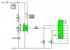
alternatively, u could use something like the circuit below, which uses a 555 as a Astable, and a 4017 decade counter, which resets on the third output, so that the first two ouputs flash on and off in sequence whenever the push switch is pressed. The values of the components are such that it would flash sooooo fast that you would not be able to let go of the switch on one particular output (head or tails) so it is effectivly random.
The circuits submitted by Styx and grrr_arrghh are unnecessarily complex.
You could simply connect the LEDs to the output of the 555. When it is stopped, one or the other will be lit. In case the mark/space ratio of the 555 is not exactly 50/50, then a J,K Flip Flop could be used to divide the output of the 555 by 2 thus providing the 50/50 signal.
This site uses cookies to help personalise content, tailor your experience and to keep you logged in if you register.
By continuing to use this site, you are consenting to our use of cookies.