Electro Tech is an online community (with over 170,000 members) who enjoy talking about and building electronic circuits, projects and gadgets. To participate you need to register. Registration is free. Click here to register now.
Welcome to our site! Electro Tech is an online community (with over 170,000 members) who enjoy talking about and building electronic circuits, projects and gadgets. To participate you need to register. Registration is free. Click here to register now.
As long as the coil current is within the maximum contact current rating for the reed. First, determine the motor's maximum current. Then, find the smallest relay that will handle the motor current. Last, find reed switches that will handle the relay's coil current.
That's the theory. But, I decided to backtrack the thread and realized that in my circuit, the limit switches are one NO (normally-open) and one NC (normally-closed). Reed switches are most frequently NO. Again a "but", the little door/window reed switch modules for home security alarms are usually NC. So that means you will need to find a source for that.
"Microswitches" are another "simple" possibility. They work like reed switches, except use a sensitive lever instead of a magnet. I think at this point you need to really detail you mechanical operation with a single, reversing motor. That way it would be easier to determine which is best.
A switch is pressed and a motor is started, the hook pulls planedown
2. **broken link removed**
Magnet is brung close to a reed switch (placed near motor), o the reed switch starts a DPDT relay. the relay switches the direction of the motor
So the plane goes up again, so now do i need another reed switch at the top to make it go back down? What if the reed switch at the top attracts the magnet when it is in the starting positiopn?
i really am lost
+
i dont know how to do the circuit for this
EDIT: could I make it so when the plane goes back up, you press the starting button again so it repeats the process. So there won't be a reed switch at the top. you would just have to press the button again to make it go down and up again. I think its a better idea.
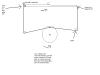
OK here's my mind's view of the mechanics with a circuit that changes motor direction, based on my original circuit with one N.O. reed and one N.C. reed. The reeds and magnets marked "A" are one possible location, and the ones marked "B" are another. Whichever is more convenient.
a metal tube with metal ballbearing.
plane tilts, closes contacts, triggers 555 for desired off time. motor starts again and tilts in oposite direction and stops when ball makes contact.
the flashing lights = add another led and resistor from (v+ to pin 3 output)
then you have alternating flashing lights.
can you use a 556 (2-555 in one package)
you must use a very slow rotating motor or a different pully combonation to achieve a slow tilt.
you could bend the tube slightly so the plane will tilt more before contact or have 2 magnets on the large wheel connected to the wing strings then when the magnet closes the reed switch contacts the motor stops (trigger the 555 timer.
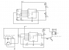
OK, another possibility. Still requires one normally-closed reed switch, but the motor only turns in one direction. The circuit allows you to push the button, the motor banks the airplane >left>level>right>level>stop.
using the post with two pullies but you don't need the metal tube.
the wheel attached to the motor has 2 narrow slits 180 degrees apart so when the IR switch conducts it triggers the 555 (momentium should close the IR switch using very narrow slit so 555 can time out and restart motor.
the flashing lights alternate at .68hz
one motor, one switch. install pushbutton between pin 2 and ground to start timmer.
the relay is connected to motor. you might have to recaculate the base resistor
NOTE I have wrong transistor should be PNP so motor is off durring the 555 on cycle. move the relay to the emitter not collector.
Do some work by searching about transistor switches.
i think a simple flip flop along with micro switches for both ends can work better to switch the motor in both direction, a transister driven relay can drive it at the end.
instead of flip flop four two input nand gates can do the job that comes in 4011 logic package.
just a wheel with both wing tips attached via a fishing line or ?
think of a crankshaft with two connecting rods in oposite directions.
one goes left while the opossing rod goes right equally.
can't get any easier bthan that.
no need for fancy flip flops to reverse the motor.\
just an IR emitter/detector slot switch
**broken link removed**
when the slotted wheel closes the switch the motor stops, times out then starts again tilting the oposite wing.
thanks a lot guys, i rly rly appreciate it. oh nd btw i didnt wait until the end, i do hav other work u knw and it jst happens dat electronics is my most hated subject. worst thing is i got forced into doing it by my parents bcos they think it wud b useful if i want 2 b an engineer (dunno hw they thought that ) :/
ok all mechanisms is on the side now and i have handed in my diagrams etc 4 mechanisms. Now all ineed 2 do it hand in the final circuit and the PCB drawing of it
i will post it here once i am finished so u guys can look and tell me if its wrong (which i knw it will be :/)
Right now I am going to stick with my orignal mechanism idea (as i have alrdy handed in the work for it) but this is what i want the circuit to EXACTLY do
1. button is pressed to start the motor
2. wing comes down
3. magnet on the wing touches a reed switch which starts a DPDT relay, which then reverses the motor
4. The wing moves back up into its ORIGINAL position and STOPS
And if you want it to repeat, you would have to press the START button again. So nothing happens automatically, it goes dwn and comes back up. then u hav to press the button again to repeat.
i am trying to do the circuit for this.
Thanks sooooooooooo much again, u guys dnt knw hw much i appreicate it. if u guys want, i will make my mum send u her special home made curry for u guys (its delicious). jus PM me
This site uses cookies to help personalise content, tailor your experience and to keep you logged in if you register.
By continuing to use this site, you are consenting to our use of cookies.

") But, I decided to backtrack the thread and realized that in my circuit, the limit switches are one NO (normally-open) and one NC (normally-closed). Reed switches are most frequently NO. Again a "but", the little door/window reed switch modules for home security alarms are usually NC. So that means you will need to find a source for that.
But, I decided to backtrack the thread and realized that in my circuit, the limit switches are one NO (normally-open) and one NC (normally-closed). Reed switches are most frequently NO. Again a "but", the little door/window reed switch modules for home security alarms are usually NC. So that means you will need to find a source for that.