Electro Tech is an online community (with over 170,000 members) who enjoy talking about and building electronic circuits, projects and gadgets. To participate you need to register. Registration is free. Click here to register now.
Welcome to our site! Electro Tech is an online community (with over 170,000 members) who enjoy talking about and building electronic circuits, projects and gadgets. To participate you need to register. Registration is free. Click here to register now.
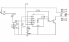
For timed switching you have the right circuit.
Problem 1: the 10uF capacitor is not needed
problem 2: you need a diode across the relay coil (diode's+ toward +9v) to protect the 555
problem 3: the timing components will be switching the relay ON for 0.065 seconds and OFF for 0.027 seconds. Way too fast. To colculate timing resistors and caps: **broken link removed**
problem 4: (the big one) timed-reversing mechanical systems will allways "creep" in one direction or the other after several cycles, and not return to the starting place. Even if the timing for both directions is exactly the same, mechanical systems tend to have a little more drag, and move a little slower in one direction. If the wing banks 5.0 cm down in 5 seconds and returns only 4.95cm in 5 seconds, it will eventually not return to the original starting position. That's why people use limit switches to reverse, rather than time.
going with a reversing circuit to tilt wing in opposite direction is long way around this project
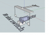
all that is needed is a ir slot interrupter switch, motor and 555 timing circuit for the 5 seconds or desired time.
no confabulated relays needed.
no reversing of motor
no issues of tearing a wing off etc. (if one string is slightly longer then you could tear off a wing)
just have the ir slot switch trigger the timer and the timer turns off the motor for determine time. OPB837L51 Optek Photointerruptors
555 circuit is just a monostable triggered timer using either 2 - 555's or 1-556, couple of resistors and capacitors.
can't be any simpler.
going with a reversing circuit to tilt wing in opposite direction is long way around this project
all that is needed is a ir slot interrupter switch, motor and 555 timing circuit for the 5 seconds or desired time.
no confabulated relays needed.
no reversing of motor
no issues of tearing a wing off etc. (if one string is slightly longer then you could tear off a wing)
just have the ir slot switch trigger the timer and the timer turns off the motor for determine time. OPB837L51 Optek Photointerruptors
555 circuit is just a monostable triggered timer using either 2 - 555's or 1-556, couple of resistors and capacitors.
can't be any simpler.
using the schematic you posted using a 640K, 300K and a 100nf you get .06151 seconds HIGH and .020 LOW
with a 75% duty cycle
no where near the 5 seconds you were talking about??
If you intend on reversing the motor using a relay then your timing circuit is way off.
here is the same 555 circuit but set up for 5.1 seconds HIGH output and 4.8 seconds LOW output with a 51% duty cycle **broken link removed**
If you can't use the slot interupter switch then how about a reed switch which is controlled by a magnet on the rotating wheel.
same circuit
This site uses cookies to help personalise content, tailor your experience and to keep you logged in if you register.
By continuing to use this site, you are consenting to our use of cookies.