Hi .. I am new 
") and I don't have experience to mikroC in my first test motor servo with Pic16F877A , if anyone can help me so i will be glad so much. how writing too simple program can i control angle in servo motor run some time Left and return Right ?. please anyone help me. thank all of
and I don't have experience to mikroC in my first test motor servo with Pic16F877A , if anyone can help me so i will be glad so much. how writing too simple program can i control angle in servo motor run some time Left and return Right ?. please anyone help me. thank all of
and I don't have experience to mikroC in my first test motor servo with Pic16F877A , if anyone can help me so i will be glad so much. how writing too simple program can i control angle in servo motor run some time Left and return Right ?. please anyone help me. thank all of
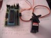
 , the truth, I tried writing a program to move left and right motor servo with( Pic16F877A) periodically, but the problem is moving in one direction, I did not know what is the problem Does anyone can write a simple program so that the experience, learn them
 A tribute to all, I do not have a lot of experience in programming, but easy is to try to help and I hope I wrote a simple program I do not know may be a big mistake, or far from the target and use the program mikroC