Hi Folks,
I am working at the moment with Pioneer a-307r. My amp microcomputer PD5443A fail. So I decide remove microcomputer. This IC controls Input selection, Direct, Loudness function, speaker Protection function . I dont need this. I need only speaker Protection function. Does anyone can build my wiring diagram for speaker protection? Please look picture. I believe it needed only 1 transistor and few resistors to get it work.
Thanks.
Services manual here.
**broken link removed**
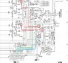
") U just need add resistor with cap (switching after 5s) protection relay wont turn ON if speaker A/B line dont switch mosfet q333; q335
U just need add resistor with cap (switching after 5s) protection relay wont turn ON if speaker A/B line dont switch mosfet q333; q335