Continue to Site

Welcome to our site!

Electro Tech is an online community (with over 170,000 members) who enjoy talking about and building electronic circuits, projects and gadgets. To participate you need to register. Registration is free. Click here to register now.

  • Welcome to our site! Electro Tech is an online community (with over 170,000 members) who enjoy talking about and building electronic circuits, projects and gadgets. To participate you need to register. Registration is free. Click here to register now.

Pinout or schematic of this big solid state relay

Status
Not open for further replies.

AlainB

Member
Hi,

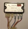
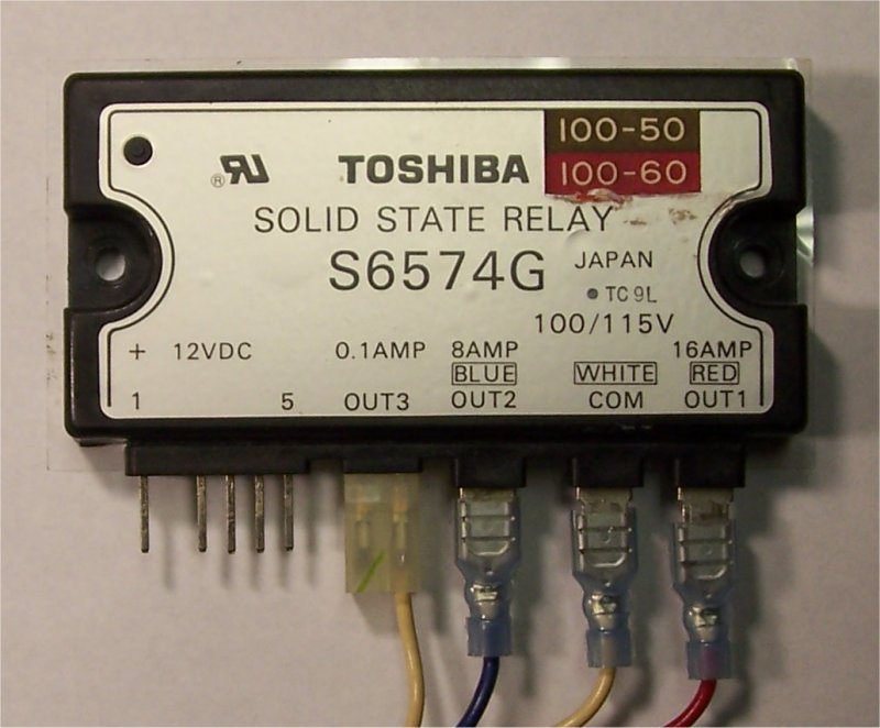
I salvaged this part along with a huge amount of other parts from a commercial photocopier.

I did not found any datasheet and my supposition is that it is an AC relay driven by the 12 volts DC pins. There was a 120-60 sticker that I removes to read under so it should also work at 120volts/60Hz.

Unfortunately, the 12 volts pinout is not obvious. Not to me anyway.

How could I test this thing without risking to burn it?

Alain

solidstaterelay-jpg.29892
 

Attachments

  • SolidStateRelay.jpg
    SolidStateRelay.jpg
    75 KB · Views: 1,194
Last edited:
Hi Alain,

if you salvaged that relay from the copier you certainly still have the connector for the 12V line somewhere in the machine. The pin labelling on the enclosure suggests pin1 as +12V and pin 5 as ground.

Looking at the connector it should only have two wires connected to it.

Boncuk
 
Hi,

Thanks for the idea. I found the connector. I should have think of that by myself! I am so dumb sometimes.

Anyway!

So this nice part happend to be a 3 in one SSR. 3 differents relays, the outputs controlled each one by the negative 12v wire applied to pin 2,3 or 4. Pin 5 is not connected.

I will certainly use it some day.

Alain
 

Attachments

  • SolidStateRelay2.jpg
    SolidStateRelay2.jpg
    77.6 KB · Views: 537
Very nice find.
 
Status
Not open for further replies.

Latest threads

New Articles From Microcontroller Tips

Back
Top