Continue to Site

Welcome to our site!

Electro Tech is an online community (with over 170,000 members) who enjoy talking about and building electronic circuits, projects and gadgets. To participate you need to register. Registration is free. Click here to register now.

  • Welcome to our site! Electro Tech is an online community (with over 170,000 members) who enjoy talking about and building electronic circuits, projects and gadgets. To participate you need to register. Registration is free. Click here to register now.

Piezo Transducer - Auto Resonant Frequency

Status
Not open for further replies.
Allrighty...

I put the scope on the transducer ... and its actually seeing about 40v pk...

Each amp is supposed to be able to handle 100 watts...

I could invert the input to one of the amps and then bridge them... but then I would lose my ground.... this would give me 80v pk...
Since the trnasducer body is one of the conenctions... I really don't want to sacrifice my ground...

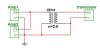
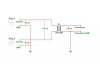
So... wouild it be possible to use a transformer with one side grounded and run the amps in parallel? Here is a schematic...

The transformer ratio would be 2.75... Would a common/standard transformer work at 28kHz??

Thanks,
Michael
 

Attachments

  • xfmr conctns.jpg
    xfmr conctns.jpg
    41 KB · Views: 155
Hey~~

Seems like I would need a autotransformer with a powered iron core for high frequency...

Perhaps it would be more efficient to toss the amps and just switch the rectifed mains voltage ... We get 220ac here in South Korea..
But since I already have the amps I think I wil lgo looking for an autotransformer with a powdered iron core...

Could someone confirm that this would be a possible solution??

Thanks,
Michael
 
Would a common/standard transformer work at 28kHz??
No, a mains transformer would not work.
Seems like I would need a autotransformer with a powered iron core for high frequency...
Use a powered iron core transformer with isolated windings. Drive the primary with the bridged amplifiers and the isolated secondary can connect to the transducer and ground. You'll probably have to wind your own transformer. This is assuming that the amplifiers can put out 200W in bridged mode.
 
Allright....

So I should invert the signal to one of the amps and tie their grounds together.... and drive the primary of the transformer with the signal form amp 1 and the inverted signal form amp 2...

Here is a pic...

Thanks,
Michael
 

Attachments

  • xfmr copy.jpg
    xfmr copy.jpg
    45.4 KB · Views: 152
Hi agian....

Since I'm having a hard time finding a suitable transformer....

I think I will start from scratch and build an amp that will deliver the 77 VRMS without using a transformer on the output...

For comparitive purposes... A 1.5 kW amp driving a 4ohm load would output 77 VRMS I need...

Into a 30 ohm load... there would a considerable surplus of current ...
So I should be able to hack away some of the output transistors...

I should prolly start a new thread for this since its a bit off topic of the original...

Thanks for everyone who helped...
Michael
 
Just Make a transformer. Its not that difficult and definately cheaper than what your proposing below.

A Ferrite "E/I" core would be best considering the frequency involved. And it should be a Power ferrite Material, such as made by "Fair Rite" and there material "77".

Total transformer cost probably under $5.00

And Why would you need a 1.5 Kw Amp to drive this?
Piezos are usually more of a Voltage operated device, rather than high current or power.

Good Luck....Gary

krazatchu said:
Hi agian....

Since I'm having a hard time finding a suitable transformer....

I think I will start from scratch and build an amp that will deliver the 77 VRMS without using a transformer on the output...

For comparitive purposes... A 1.5 kW amp driving a 4ohm load would output 77 VRMS I need...

Into a 30 ohm load... there would a considerable surplus of current ...
So I should be able to hack away some of the output transistors...

I should prolly start a new thread for this since its a bit off topic of the original...

Thanks for everyone who helped...
Michael
 
Hi~

The comment I make about the 1.5kw amp ...was, as I said, for comparative purposes...

As, it would require the same voltage (77 VRMS) to drive 1.5kw into a 4 ohm load...
As 200 watts would be into a 30 ohm load... (77 VRMS)

On the line under that, I mentioned "there would a considerable surplus of current ..."
And I could remove some of the output transistors as to remove the current surplus...

As for using a transformer... thanks for the tip about making one...
However.... I have been advised that the kit amps I already have (based on 2sc5200 and 2sa1943) will prolly not handle 200 watts at 28 khz...

So I might as well start from the beginning.... and just build an amp that doesnt need an output trasformer...

Which is what Im currently doing... found a schematic online for an amp that will take +/- 125 VDC... (not the 117 from esp)...
Monday I will prolly pick up the parts for it...

Thanks,
Michael
 
Status
Not open for further replies.

Latest threads

Back
Top