Continue to Site

Welcome to our site!

Electro Tech is an online community (with over 170,000 members) who enjoy talking about and building electronic circuits, projects and gadgets. To participate you need to register. Registration is free. Click here to register now.

  • Welcome to our site! Electro Tech is an online community (with over 170,000 members) who enjoy talking about and building electronic circuits, projects and gadgets. To participate you need to register. Registration is free. Click here to register now.

Piezo Transducer - Auto Resonant Frequency

Status
Not open for further replies.

krazatchu

Member
Hello all,

I have a piezo transducer meant for welding and/or cleaning...

It will be used to set a "structure" into a resonant vibration... Not the first mode of vibration but rather a higher mode in the range of 20kHz to 30kHz..

It will be bolted to the structure and the structure may undergo some change... therefore it's resonant frequency will depend on the structure and will vary unpredictably...

I would like to be able to indicated when its operating at its resonant frequency...

As I understand, it will be at it's resonant frequency when the impedance is at it's lowest...

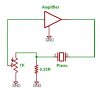
I have seen a method where the transducer is connected in series with a resistor... A scope across the transducer will indicate a relative impedance...

However... as I would like to drive the transducer while checking for resonance... What and/or how should I be measuring???


The specs of the transducer are as follows:
Resonant frequency: 28 kHz
Resonant impedance: 30 Ohm max
Static capacitance: 2500 pf
Max operating power: 200 Watts
Lenght dimension: 91.4 mm
Diameter dimension: 30 mm

Thanks,
Michael
 
Hello~~

I have been doing some research on resonant frequency tracking....

I have uncovered a few different methods of actively foloowing the resonant frequency...

They are as follows...

1) Vibration amplitude sensor mounted on piezo transducer...
This method would require a memory to determine if the amplitude is increasing or decreasing... and then increase or decrease the frequency accordingly...

2) PLL - measuring the phase angle between voltage and current, when phase angle difference = zero... system is at resonance...
I'm not completely clear on the implementation of this...

3) Admittance locking... I have no idea what this is yet...
Here is a link to an abstract, I don't have access to the full article...
**broken link removed**

So.... Could anyone weigh in on these methods... ??
I would like to create something as simple and as cheap as possible... perhaps something I could fit on a AVR with minimal circuitry...
I think others would benefit a piezo driver that locks on resonant frequency...

Thanks,
Michael
 
Since the piezo already has a resonant frequency just put it in the positive feedback loop of an amplifier and it'll oscillate at the proper frequency.
 
I'm not sure that will work as there is a mechanical resonance involved...

I think I would also have to isolate it as its running at 100v pp...

I think PLL is a pretty common method .... I just don't know how to implement that yet....
 
Assuming the following things:
The transducer is 30:eek:hm: at its resonant frequency.
You want apx 100Vpk-pk out of the amplifier.
The amplifier will output 100Vpk-pk with less than 1Vpk-pk input.
The amplifier can handle a continuous output at that level at 100% duty cycle without blowing up.
You would do something like this:
 

Attachments

  • feedback.png
    feedback.png
    5.9 KB · Views: 223
Last edited:
Great!

Thanks for the schematic... I will give that a try on Monday...

I have been working on an Oscope project from avrfreaks... but I'm having trouble with the LCD....

I recently found another elctronics market here in Korea, they seem to have alot of used stuff there... So I will go hunting for a used scope today...
Finally I will be able to see what I'm doing...

Thanks,
Michael
 
Hmm..

It seems that 0.33 ohm resistor will have to be pretty big...

Can someone clue me in how I apply ohm's law to calculate the current thru the resistor so I can figure out the power rating for the resistor...?

Using I = V / R ... and then P= I x V .... doesn't give a reasonable value...

Thanks
 
how come? what your voltage? it's a simple division..

to help you imagine that with a 12V power supply and 1 ohm resistor
you can pass 12A, with the same supply and 2 ohm resistor you can
pass 6A.
 
I'm mathimatically challenged.... just kidding... @ 100 volts I get 300 Amps...
Which gives a power of 30 kw....

Obviously I'm appling the formula incorrectly...
 
The hundred volts will be across the piezo (30:eek:hm:) in series with the 0.33:eek:hm: so it would be 3.3Amps peak current.
100V / (30 + 0.33) = 3.3A
100v peak is 70.7Vrms so the RMS current would be 2.33 amps and the RMS power 164.8 Watts. The power dissipated in the 0.33:eek:hm: resistor would be 1.8 watts.
 
Last edited:
Hello agian~~~

A few days ago I bought a used ocilloscope, A Hung Chang 5604... 40MHz, 2 ch...
And... in attempt to avoid looking like an idiot... I have been studying up on the basics...

So, could someone please check my math on the following....

The amp I'm using is rated for 100 watts, I have 2 of these on seperate boards with seperate heatsinks...
The amp uses the Toshiba 2SC5200 and complentary 2SA1943... the datasheet on these parts says "Recommended for 100W hifi amp..."

Now... assuming the 100W rating should be for an 8:eek:hm: speaker...
So, If I calculate the current by I=V/R .. I get 12.5 Amps...
and like kchriste said, "100v peak is 70.7Vrms" ....
Then, using the RMS voltage, the RMS current is 8.75 Amps..
And the RMS power is P = V*I = 618.625 W .... Wrong again..

Hmm... still looking stupid... time to study more...
 
Ok... it seems a speaker is a reactive load as well as a resistive load....

So I have to use trig to calculate this? Is this correct?
 
Last edited:
Hmm...

Kchriste, shouldn't the calucluation be done with 50V peak and not 100V peak...
The amp is being supplied with +/- 50 volts dc....
It's output is gnd & signal ... which is good as it allows me to ground the transducer...
100v peak is 70.7Vrms so the RMS current would be 2.33 amps and the RMS power 164.8 Watts.
Since the peak voltage is half of the peak to peak?

So... RMS voltage would be 35.35Vrms and then curent would be 1.17A rms..
which makes the RMS power 41.4 watts...

Am I right, wrong or totally confused?
 
Last edited:
Allrighty...

If my corection above is right... And I want to calculate what voltage I should be driving the transducer at, for maximum power of 200 watts.... then....

Using V = SQRT(P * R) = SQRT(200 * 30.33) = 77.9 V RMS
Which is 110.1 Volts peak .... So I should be running +/- 110 Volts into the transducer...

Is this correct?
 
Last edited:
Yes, you'd need apx 110Vpk (77.9 RMS) into a 30:eek:hm: load to get 200 watts.
 
Status
Not open for further replies.

Latest threads

New Articles From Microcontroller Tips

Back
Top