Continue to Site

Welcome to our site!

Electro Tech is an online community (with over 170,000 members) who enjoy talking about and building electronic circuits, projects and gadgets. To participate you need to register. Registration is free. Click here to register now.

  • Welcome to our site! Electro Tech is an online community (with over 170,000 members) who enjoy talking about and building electronic circuits, projects and gadgets. To participate you need to register. Registration is free. Click here to register now.

Pickit 3 led flashing, normal or not?

Status
Not open for further replies.

Kal_B

Member
Hello everyone,
I'm brand new to micro-controllers and started with PIC16F876A and a Pickit3 programmer.
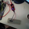
I wired it up and fired up MPLAB x IDE V5.4 and after a couple of days of reading and watching youtube I configured it to be powered up via the USB port with 4.5VDC.
I was able to download a basic program with no errors but can not get a red LED connected to RB4 to illuminate and while troubleshooting I couldn't figure out if a flashing red LED is normal.
It is right beside the Status LED and flashing at a steady rate which I think is every second. (Note: it appears to flash slower in the posted gif than real life)
Any ideas?
Thanks
 

Attachments

  • fx33EyIqrT.gif
    fx33EyIqrT.gif
    46.1 MB · Views: 318
I think I know why my LED did not work and that is because I did not have an oscillator connected to the chip and will have to buy one next week.
It would be nice to know though the deal with that flashing LED in the Pickit3
Thanks
 
Last edited:
Just powered up my PicKit 3 and the power and active lights are lit and the status isn't. According to the manual page 39 the error (assuming continuous flashing) is that the PicKit isn't able to set Vdd or Vpp (more likely) to the correct voltage. Check your wiring.

Mike.
 
Just powered up my PicKit 3 and the power and active lights are lit and the status isn't. According to the manual page 39 the error (assuming continuous flashing) is that the PicKit isn't able to set Vdd or Vpp (more likely) to the correct voltage. Check your wiring.

In my experience it's usually Vdd that gives problems, as the PK3 can only supply a small amount of current - a big advantage of the PK4 is that can supply considerably more. Depending what's connected to the PIC it may not work when powered from the PK3, even an Hitachi type LCD is often enough to stop it working. 'Usually' you don't have anything connected to the MCLR pin, other than a 10K resistor to Vdd.
 
Thanks guys.
I don't see it. I checked the wiring and removed the LED I had connected and the result is the same. To add more information, below is the output after I connect the USB and MPLAB-X detects and powers the kit.
When I first connect the kit and the output is finished I get LED light up as in picture, Power=Green-Active=Blue-Status=Green. If I click on the "Refresh Debug Tool Status" I get the same result, everything looking good; no flashing red.

Then I click on "Make and Program Device Main Project" and at the bottom of the output window I get Programming/Verify complete, and that's when the LED starts flashing.

I will post a link to a youtube video to show the difference between the status LED being red when programming the chip vs after. The flash after seems to be smaller and to the side of the Status LED.

Here's the link to the video.

Thanks


Code:
// CONFIG
#pragma config FOSC = HS        // Oscillator Selection bits (HS oscillator)
#pragma config WDTE = OFF       // Watchdog Timer Enable bit (WDT disabled)
#pragma config PWRTE = OFF      // Power-up Timer Enable bit (PWRT disabled)
#pragma config BOREN = OFF      // Brown-out Reset Enable bit (BOR disabled)
#pragma config LVP = OFF        // Low-Voltage (Single-Supply) In-Circuit Serial Programming Enable bit (RB3 is digital I/O, HV on MCLR must be used for programming)
#pragma config CPD = OFF        // Data EEPROM Memory Code Protection bit (Data EEPROM code protection off)
#pragma config WRT = OFF        // Flash Program Memory Write Enable bits (Write protection off; all program memory may be written to by EECON control)
#pragma config CP = OFF         // Flash Program Memory Code Protection bit (Code protection off)

// #pragma config statements should precede project file includes.
// Use project enums instead of #define for ON and OFF.

#include <xc.h>
//#define _XTAL_FREQ 20000000 //Specify the XTAL crystal FREQ
void main() //The main function
{
TRISB=0X00; //Instruct the MCU that the PORTB pins are used as Output.
PORTB=0X00; //Make all output of RB LOW
while (1){
    PORTB=0b01111100;
    ;
}

PICkit 3 connected

*****************************************************

Connecting to MPLAB PICkit 3...

Currently loaded firmware on PICkit 3
Firmware Suite Version.....01.56.07
Firmware type..............Midrange

Programmer to target power is enabled - VDD = 4.875000 volts.
Target device PIC16F876A found.
Device Revision ID = 8
 

Attachments

  • IMG_20200614_114200.jpg
    IMG_20200614_114200.jpg
    1,018.3 KB · Views: 279
Last edited:
I've never been able to successfully power any chip with the PicKit3. I always use a separate power supply to power it. Are you able to power it this way?

Mike.
Edit, as it successfully programs it then I suspect it's Vdd that isn't high enough - if it was Vpp then it wouldn't program.
Edit, just looked at your image and there's no crystal or capacitors that are needed with the 876.
Edit again, do you have any chips that have an internal oscillator such as the 16F886?
 
Last edited:
Thanks Mike. I really have no clue what I'm doing and got into this in a strange time as I'm traveling and thought I could play with it in my room when I have time but I have no access to parts or even a meter. I travel with a small PLC kit on regular basis that I use for work and porgram testing and thought I would do the same with a microcontroller to learn them. I think I should've purchased a development board *but* this mistake made me read a lot more and may end up being more beneficial.

To answer your questions, I only tried powering it up with USB and don't have capacitors nor oscillator, I just grabbed resistors and LEDs and thought that was all I needed. I will update once I had an opportunity to more parts and set it up properly.

Thanks a lot.
 
I would recommend getting a chip with an internal oscillator. Some of the newer ones will run at 32MHz without any external components. The 16F886 (which replaced the 16F876A) has an 8MHz internal oscillator. You may be able to get one from a local electronics shop.

Mike.
 
I've never been able to successfully power any chip with the PicKit3. I always use a separate power supply to power it. Are you able to power it this way?

I've done countless projects powered from the PK3 while programming, but it's certainly 'hit and miss' - I've even managed to do some where there's an Hitachi LCD in circuit, but I suspect that's 'right on the edge' as it sometimes works, and sometimes doesn't. But some circuits you can never get to work at all, and have to provide external power - just a little bit more available current would make a HUGE difference, and of course that's what the PK4 provides.
 
I would recommend getting a chip with an internal oscillator. Some of the newer ones will run at 32MHz without any external components. The 16F886 (which replaced the 16F876A) has an 8MHz internal oscillator. You may be able to get one from a local electronics shop.

I also like the 18F27K40/42 which has massive memory, and can run at 64MHz internally.

I've always liked the internal oscillators (which was why I choose the 628 for my tutorials), it's one less thing to worry about, gives you two extra I/O pins, and is perfectly accurate enough for the majority of applications.
 
I like the newer chips due to the long list of peripherals, huge memory etc. However, I feel the OP should avoid them due to their complexity. Trying to setup the PPS module is a nightmare. Something like the 886 should be ideal to get started with or even the 16f628!!

Mike.
 
I like the newer chips due to the long list of peripherals, huge memory etc. However, I feel the OP should avoid them due to their complexity. Trying to setup the PPS module is a nightmare. Something like the 886 should be ideal to get started with or even the 16f628!!

True, they are a nightmare to configure - but that's where MCC comes in.

I tend to configure it using MCC, and then cut & paste the setup code I want.

I've taken to using separate setup files (like settings_16F18857.c and .h etc.) and then just include it in the main file - if you change PIC's, then you simply change the setup file for a different one. Most of the time you tend to use the same clock speed, and you can easily place a couple of commented out lines in the file for different speeds.
 
Agree completely but still think the op will be better starting with one of the older chips.

Mike.
 
He using C don't really matter if he used a new chip just set the chip up with MCC
and then write all the C code you want.

It's easy setting a chip up with MCC
 
MPLAB X IDE takes care of configuration. MOLAB Xpress is online so even easier because no setup on your PC.
 
So the only chip I could find locally is the PIC15F2520 and bought two of them

Before I get into asking more questions about more problems let me ask this:

Is this the best way to start learning microcontrollers?
So far it's been a nightmare and I generally have very little patience with crappy products and specially software which MPLAB definitely is.; garbage.
The resources on the internet are very old specially the ones from microchip and not ordered in any way.
So should I look for another MCU and if yes which one has the best support, software and documentation/

Thanks
Kal
 
I assume you mean PIC18F2520. If so, that's an old but good chip. As you say, MPLABX isn't the best software around but is usable. See if you can get the config settings that work and try for a flashing LED first. I have used that chip in the past so can probably put together a simple demo if you get stuck.

Mike.
 
Status
Not open for further replies.

Latest threads

New Articles From Microcontroller Tips

Back
Top